Vehicle control method, device and plant and terminal

A vehicle control and target vehicle technology, which is applied in the field of vehicle control, can solve the problems of uneven deceleration process, fluctuation of deceleration, affecting driving experience, etc., and achieve the effect of ensuring real-time performance and smoothness

Active Publication Date: 2019-08-09
ZHEJIANG GEELY HLDG GRP CO LTD +1
View PDF5 Cites 5 Cited by
  • Summary
  • Abstract
  • Description
  • Claims
  • Application Information

AI Technical Summary

Problems solved by technology

When the vehicle decelerates, from a certain low speed (such as 5km / h) to the stage of stopping, the distance between the self-vehicle and the vehicle in front detected by the radar fluctuates up and down in a wave shape, resulting in the deceleration also fluctuating up and down in a wave shape , so that the deceleration process at this stage is not smooth, seriously affecting the driving experience
[0003] In order to solve the problem of fluctuations in the deceleration calculated by the radar when the vehicle is at a low speed, the current conventional method is to filter the deceleration sent by the radar; to filter the deceleration sent by the radar, the filtering effect depends on the order of the filter, the filtering The higher the order, the better the filtering effect; however, if high-order filtering is implemented by hardware, the precision of the hardware is very high, which will increase the hardware cost of the vehicle; but if it is implemented by software, the delay of filtering calculation is relatively large , will affect the real-time performance of vehicle response

Method used


Image

  • Vehicle control method, device and plant and terminal
  • Vehicle control method, device and plant and terminal
  • Vehicle control method, device and plant and terminal

Examples


Embodiment Construction

[0057] The following will clearly and completely describe the technical solutions in the embodiments of the present invention with reference to the accompanying drawings in the embodiments of the present invention. Obviously, the described embodiments are only some, not all, embodiments of the present invention. Based on the embodiments of the present invention, all other embodiments obtained by persons of ordinary skill in the art without making creative efforts belong to the protection scope of the present invention.

[0058]It should be noted that the terms "first" and "second" in the description and claims of the present invention and the above drawings are used to distinguish similar objects, but not necessarily used to describe a specific sequence or sequence. It is to be understood that the data so used are interchangeable under appropriate circumstances such that the embodiments of the invention described herein can be practiced in sequences other than those illustrated...


PUM


Abstract

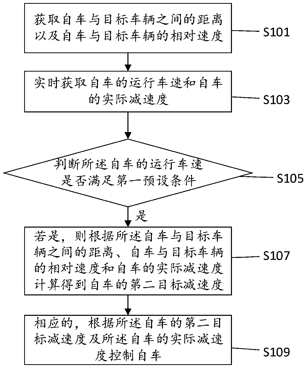
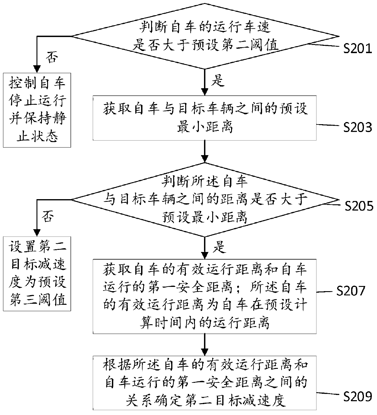
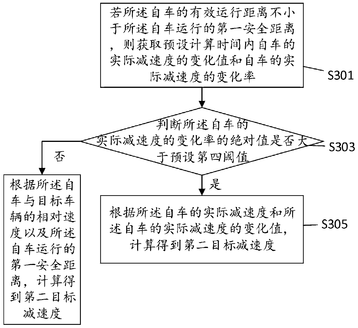
The invention discloses a vehicle control method, device and plant and a terminal. The method includes the steps that the distance between an own vehicle and a target vehicle and the relative speed ofthe own vehicle and the target vehicle are obtained; the operation vehicle speed and the actual decelerated speed of the own vehicle are obtained in real time; whether the operation vehicle speed ofthe own vehicle meets a first preset condition or not is judged; if the operation vehicle speed of the own vehicle meets the first preset condition, according to the distance between the own vehicle and the target vehicle, the relative speed of the own vehicle and the target vehicle and the actual decelerated speed of the own vehicle, the second target decelerated speed of the own vehicle is obtained through calculation; and correspondingly, according to the second target decelerated speed and the actual decelerated speed of the own vehicle, the own vehicle is controlled. When the vehicle is at a low speed, the vehicle is smoothly braked through the own vehicle second target decelerated speed obtained through calculation conducted according to the distance between the own vehicle and the target vehicle, the relative speed of the own vehicle and the target vehicle and the actual decelerated speed of the own vehicle, and the actual decelerated speed of the own vehicle; and the deceleration smoothness and the response instantaneity of the vehicle are guaranteed.

Description

technical field [0001] The present invention relates to the technical field of vehicle control, in particular to a vehicle control method, device, equipment and terminal. Background technique [0002] At present, vehicles are becoming more and more intelligent, and intelligent functions are emerging one after another, such as adaptive cruise, traffic congestion assistance, and automatic driving. The acceleration and deceleration of these functions rely on the acceleration and deceleration requests sent by the radar. When the vehicle decelerates, from a certain low speed (such as 5km / h) to the stage of stopping, the distance between the self-vehicle and the vehicle in front detected by the radar fluctuates up and down in a wave shape, resulting in the deceleration also fluctuating up and down in a wave shape , so that the deceleration process at this stage is not smooth, seriously affecting the driving experience. [0003] In order to solve the problem of fluctuations in th...

Claims


Application Information

Patent Timeline
Patent Type & Authority Applications(China)
IPC IPC(8): B60W30/14
CPCB60W30/143B60W2520/10B60W2520/105B60W2554/80B60W2554/801B60W2720/106
Inventor 冯如吉张岩王行峰赵翠发
Owner ZHEJIANG GEELY HLDG GRP CO LTD
Why Eureka
Try Eureka