
Furnace cover lifting structure of pit furnace

A technology of well-type furnace and furnace cover is applied in the field of lifting structure of well-type furnace cover, which can solve the problems of falling lubricating oil, frequent wear and replacement, stains, etc., and achieves the effect of easy maintenance and small driving force.

Pending Publication Date: 2019-08-09
HENAN TIANLI THERMOTECHNICAL EQUIP CO LTD
View PDF4 Cites 2 Cited by
  • Summary
  • Abstract
  • Description
  • Claims
  • Application Information

AI Technical Summary

Problems solved by technology

Therefore, the current domestic common steam oxidation pit furnace can no longer meet the needs of society and development
[0003] There is a furnace cover on the upper end of the well-type furnace. At present, most of them are lifted by chains. This lifting method generally includes two chains, multiple rollers and accessory parts, and also includes a hoist. This lifting method is not to be blamed; However, the maintenance of parts is more troublesome, and the number of wear and replacement is more; the lubricating oil of the chain often causes stains due to the drop of lubricating oil. , the crane is easily damaged by heat when used for a long time, and the maintenance and replacement costs are relatively high

Method used


Image

  • Furnace cover lifting structure of pit furnace
  • Furnace cover lifting structure of pit furnace
  • Furnace cover lifting structure of pit furnace

Examples


Embodiment Construction

[0016] The present invention will be described in detail below in conjunction with the accompanying drawings. It should be noted that the orientation terms such as left, middle, right, up, and down in the examples of the present invention are only relative concepts or refer to the normal use state of the product, and should not be considered as restrictive .

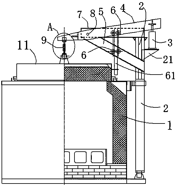
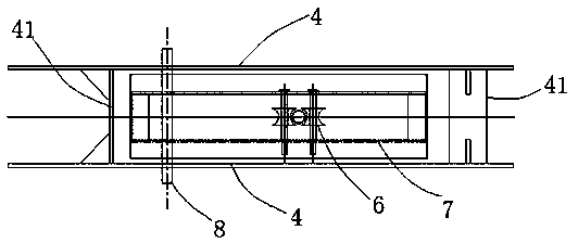
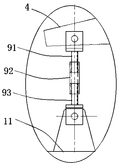
[0017] Such as figure 1 As shown, a pit-type furnace cover lifting structure includes a furnace body 1 and a furnace cover 11 arranged on the upper end of the furnace body 1, and a bracket 2 is fixed on one side of the furnace body 1, and the bracket 2 The upper end of the support arm is fixed with a support arm, the support arm includes a cross arm 7 and an oblique arm 5, the front end of the support arm extends directly above the furnace cover 11, and a lever is arranged on the support arm 4. The front end of the lever 4 is rotatably mounted on the front end of the support arm, and the front end of the lever 4 is fix...


PUM


Abstract

The invention provides a furnace cover lifting structure of a pit furnace. The structure comprises a furnace body, and a furnace cover arranged at the upper end of the furnace body; a bracket is fixedly arranged on one side of the furnace body; a support arm is fixedly arranged at the upper end of the bracket; the end part of the front end of the support arm extends right above the furnace cover;a lever is arranged on the support arm; the end part of the front end of the lever is rotationally mounted at the front end of the support arm; the front end of the lever is fixedly connected with themiddle part of the furnace cover through a connecting rod; an extension cylinder is fixedly arranged on the bracket opposite to the back end of the lever; an extension rod arranged on the extension cylinder is fixedly connected with the back end of the lever; the lever is arranged above the furnace cover; the front end of the lever is connected with the furnace cover; a power execution mechanismis arranged at the back end of the lever; the lifting and the falling are realized through the lever principle, so that the driving force is low; whole structural parts are fewer to achieve convenience to maintain, cleanness and tidiness; and a guide mechanism is arranged between the furnace cover and the support arm for covering the furnace cover on the furnace body through vertical lifting without needing assistance by operators.

Description

technical field [0001] The invention relates to the technical field of pit furnaces, in particular to a lifting structure for a furnace cover of a pit furnace. Background technique [0002] Pit furnace is a cycle heat treatment equipment, which is suitable for the treatment of rods and long shaft metal components, and is widely used in basic industrial fields such as auto parts manufacturing and mold manufacturing. With the continuous development of our country's social economy, the requirements for metal products in domestic and foreign markets continue to increase. At the same time, the manufacturers of finished products have higher and higher requirements for the surface hardness and service life of metal components. Therefore, the current domestic common steam oxidation pit furnace can no longer meet the needs of society and development. [0003] There is a furnace cover on the upper end of the well-type furnace. At present, most of them are lifted by chains. This lifti...

Claims


Application Information

Patent Timeline
Patent Type & Authority Applications(China)
IPC IPC(8): F27D1/18
CPCF27D1/1808F27D2001/1825
Inventor 贾红梅翟德梅孙国进陶凯
Owner HENAN TIANLI THERMOTECHNICAL EQUIP CO LTD
Learn More