Functional trachea cannula

A tracheal intubation, functional technology, applied in the direction of tracheal intubation, respirator, etc., can solve the problems of inconvenient fixing of the fixing device and inconvenient movement of the tracheal intubation back and forth

Active Publication Date: 2019-08-13
河南省健琪医疗器械有限公司
View PDF9 Cites 2 Cited by
  • Summary
  • Abstract
  • Description
  • Claims
  • Application Information

AI Technical Summary

Problems solved by technology

[0003] The purpose of the present invention is to provide a functional tracheal intubation to solve the technical problem that the existing fixing device for tracheal intubation is inconvenient to fix and it is also inconvenient to move back and forth along the tracheal intubation after fixing

Method used


Image

  • Functional trachea cannula
  • Functional trachea cannula
  • Functional trachea cannula

Examples


Embodiment 1

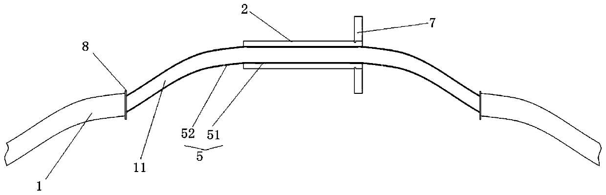
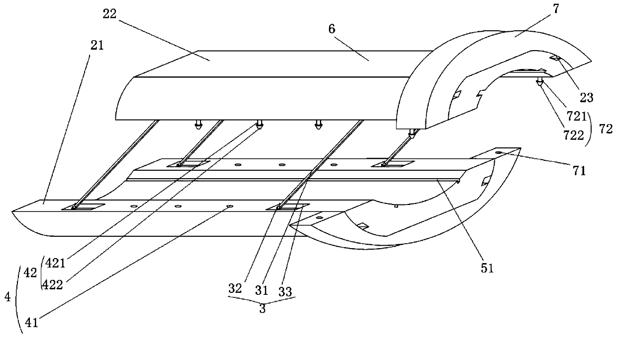
[0033] The functional endotracheal tube of this embodiment includes an endotracheal tube body 1 , a fixing sleeve 2 , a connecting component 3 , a fastening component 4 , a sliding rail component 5 , a dental pad component 6 , and a limit component.

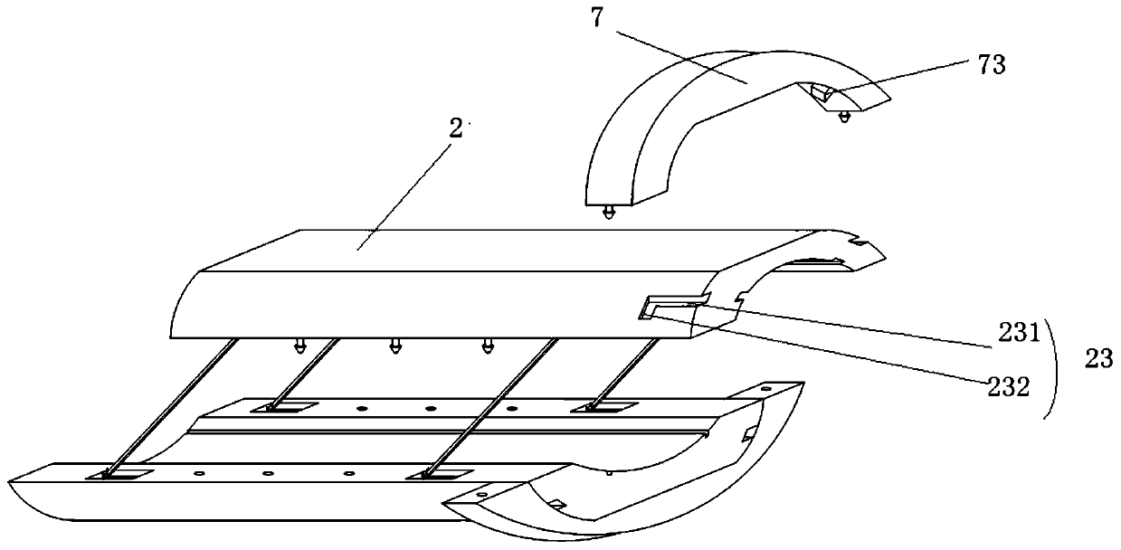
[0034] The fixing sleeve 2 is a cylindrical structure that is sheathed on the endotracheal tube body 1 and is composed of a first arched structure 21 and a second arched structure 22 surrounding a through hole structure for the endotracheal tube body 1 to pass through.

[0035] The connecting component 3 can connect the two first arch structures and the second arch structures and define the relative positions of the first arch structures and the second arch structures. The connecting assembly 3 includes a connecting rod 31, a hinge 32 for respectively hingeing the two ends of the connecting rod 31 on the first arch structure and the second arch structure, and a connecting groove for accommodating the hinge 32 and the connecting ro...

Embodiment 2

[0042] The functional endotracheal intubation described in this embodiment has a general structure consistent with that of Embodiment 1, but it is different from Embodiment 1 in that the fastening end is in the shape of a vertebral body, and the big end of the vertebral body-shaped fastening end is connected to the tight end. The fastening post 421 is connected, and the fastening post is a cylindrical structure, and the diameter of the fastening post is smaller than the diameter of the large end of the vertebral fastening end.

Embodiment 3

[0044] The general structure of the functional tracheal intubation described in this embodiment is consistent with that of Embodiment 1, but it is different from Embodiment 1 in that the limiting end is cone-shaped, and the big end of the cone-shaped limiting end is in line with the limiting end. The position post is connected, the limit post is a cylindrical structure, and the diameter of the limit post is smaller than the diameter of the big end of the cone-shaped stop end.


PUM


Abstract

The invention relates to a functional trachea cannula. The functional trachea cannula comprises a trachea cannula body, and further comprises a fixing sleeve, a connecting assembly, a fastening assembly, a slide rail assembly, a tooth cushion assembly and a limiting assembly, wherein the fixing sleeve sleeves the trachea cannula body, and is composed of a first arched structure and a second archedstructure which define a through hole structure allowing the trachea cannula body to penetrate through; the connecting assembly is used for connecting the first arched structure with the second arched structure; the fastening assembly is used for fastening the fixing sleeve on the trachea cannula body or loosening the fixing sleeve from the trachea cannula body; the slide rail assembly is used for sliding the fixing sleeve along the trachea cannula body back and forth and limiting the fixing sleeve; the tooth cushion assembly is arranged on the fixing sleeve and is used for teeth holding-on;the limiting assembly is arranged on the fixing sleeve and is used for preventing the fixing sleeve from moving to the inner portion of the oral cavity. The functional trachea cannula provides convenience for adjusting the fixing sleeve to an appropriate position to fix the trachea cannula body.

Description

technical field [0001] The invention belongs to the technical field of tracheal intubation, in particular to a functional tracheal intubation. Background technique [0002] Endotracheal intubation generally consists of intubation tube, balloon, inflation tube and suction tube components. The endotracheal tube is inserted into the trachea through the glottis. After insertion, the endotracheal tube may shake back and forth or fall off. Once the endotracheal tube slips off, it will cause further injury to the patient. In order to prevent the tracheal tube from shaking back and forth or falling off, a tracheal tube fixing device can be provided. The existing endotracheal tube fixing device and the endotracheal tube are mostly separated from the endotracheal tube, and it is difficult to fix on the endotracheal tube. After being fixed on the endotracheal tube, it is inconvenient to move back and forth along the endotracheal tube. Contents of the invention [0003] The purpose ...

Claims


Application Information

Patent Timeline
Patent Type & Authority Applications(China)
IPC IPC(8): A61M16/04
CPCA61M16/04A61M16/0497A61M16/0463A61M16/0493
Inventor 任永成万锡铭田书增陈三玲
Owner 河南省健琪医疗器械有限公司
Why Eureka
Try Eureka