
Engine controller

A technology for a control device and an engine, which is applied in the direction of engine control, combustion engine, machine/engine, etc., and can solve problems such as deterioration of drivability and increased variation of engine rotation.

Active Publication Date: 2019-08-16
TOYOTA JIDOSHA KK
View PDF16 Cites 0 Cited by
  • Summary
  • Abstract
  • Description
  • Claims
  • Application Information

AI Technical Summary

Problems solved by technology

Therefore, during the execution of the variable control of the combustion cylinder ratio, the rotation fluctuation of the engine increases, and drivability may deteriorate.

Method used


Image

  • Engine controller
  • Engine controller
  • Engine controller

Examples


Embodiment Construction

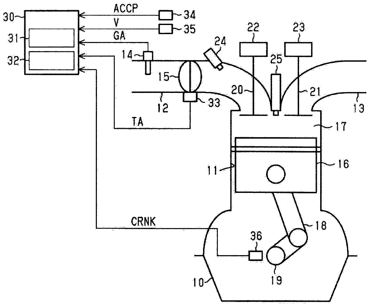
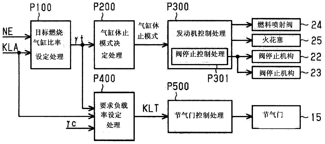
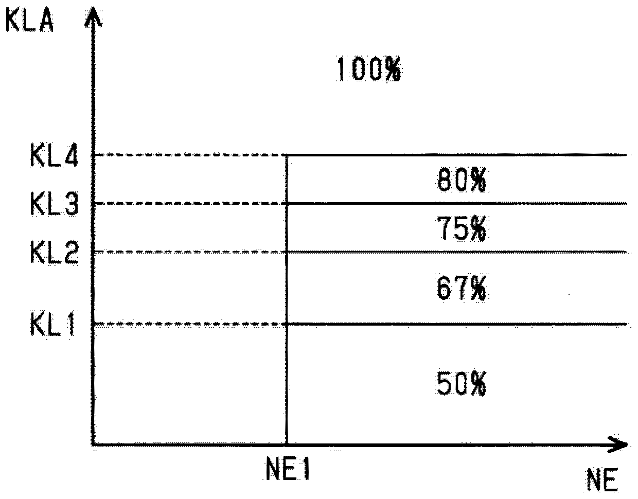
[0022] Below, refer to Figure 1 to Figure 7 , an embodiment of the engine control device will be described in detail.

[0023] figure 1 The shown engine 10 is constituted as an inline four-cylinder vehicle engine having four cylinders 11 ( figure 1 One of four cylinders 11 is shown). It should be noted that, in the following description, when the four cylinders 11 are distinguished, they are described as cylinder #1, cylinder #2, cylinder #3, and cylinder #4. Incidentally, the ignition order of the cylinders 11 in this engine 10 is in the order of cylinder #1, cylinder #3, cylinder #4, cylinder #2.

[0024] The engine 10 is provided with an intake passage 12 through which intake air flowing into each cylinder 11 flows, and an exhaust passage 13 through which exhaust gas discharged from each cylinder 11 flows. An air flow meter 14 is provided in the intake passage 12 to detect the flow rate (amount of intake air GA) of intake air flowing therein. In addition, a throttle v...


PUM


Abstract

An engine controller configured to control an engine includes a combustion cylinder ratio control unit, a valve stopping control unit, and a throttle control unit. The throttle control unit is configured to start adjusting a throttle open degree in accordance with the change of the combustion cylinder ratio at an earlier timing when the value of the combustion cylinder ratio is increased by the change than when the value of the combustion cylinder ratio is decreased by the change.

Description

technical field [0001] The present invention relates to an engine control device that performs variable control of the ratio of combustion cylinders. Background technique [0002] U.S. Patent No. 9,200,575 describes performing an intermittent combustion operation based on intermittent cylinder deactivation, and changing the frequency of cylinder deactivation in the intermittent combustion operation to perform the combustion cylinder ratio of the engine [=the number of combustion cylinders / (the number of combustion cylinders + stop cylinder number)] variable control technology. In addition, this document shows that various combustion cylinder ratios can be realized by dynamically changing the deactivated cylinders without fixing the deactivated cylinders as specific cylinders. [0003] On the other hand, Japanese Patent Application Laid-Open No. 2005-105869 describes stopping the opening and closing operation of the intake / exhaust valves of the cylinders whose combustion is ...

Claims


Application Information

Patent Timeline
IPC IPC(8): F02D17/02
CPCF02D17/02F02D41/0087F02D41/0002F02D2041/0012F02D2041/002F02D2200/0404F02D2200/0406F02D13/06Y02T10/12Y02T10/40F02D2009/0235F02D13/0223F02D9/02
Inventor 中野智洋
Owner TOYOTA JIDOSHA KK
Learn More