Visual servo robot measurement time-delay compensation method

A technology of visual servoing and compensation methods, which is applied in the direction of manipulators, program control manipulators, manufacturing tools, etc., can solve the problems of high model accuracy, slow dynamic response, and affecting accuracy, so as to improve robustness and control accuracy. Improvement of servo control performance and improvement of dynamic response speed

Inactive Publication Date: 2019-12-27
南京隆越自动化科技有限公司
View PDF0 Cites 0 Cited by
  • Summary
  • Abstract
  • Description
  • Claims
  • Application Information

AI Technical Summary

Problems solved by technology

The traditional control method does not consider the measurement time lag in the design, so in order to ensure the stability of the system, only a slow dynamic response can be selected when adjusting the controller parameters, and it is difficult to achieve high-performance servo control effects
When compensating for disturbances in visual servoing systems, classical disturbance estimator-based methods also suffer from measurement time-lags, reducing the effectiveness of disturbance compensation
When the visual servo robot tracks an unknown trajectory, the measurement time lag will seriously affect the accuracy of the existing prediction methods, resulting in low tracking accuracy and slow tracking speed
[0004] For the measurement time lag existing in the visual servo robot, the Smith predictor is usually used in the existing visual measurement time lag compensation, but this method has high requirements on the accuracy of the model built by the system, which is difficult to meet in practical applications.
Other compensation methods do not consider the existence of interference in the system, which does not conform to the actual situation of the visual servo robot system and reduces the control performance of the system

Method used


Image

  • Visual servo robot measurement time-delay compensation method
  • Visual servo robot measurement time-delay compensation method
  • Visual servo robot measurement time-delay compensation method

Examples


Embodiment Construction

[0025] The present invention is further clarified in conjunction with the accompanying drawings and specific embodiments. It should be understood that the following specific embodiments are only used to illustrate the present invention but not to limit the scope of the present invention.

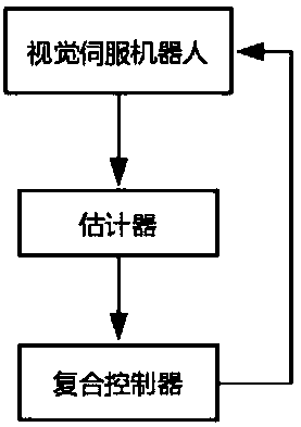
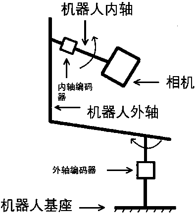
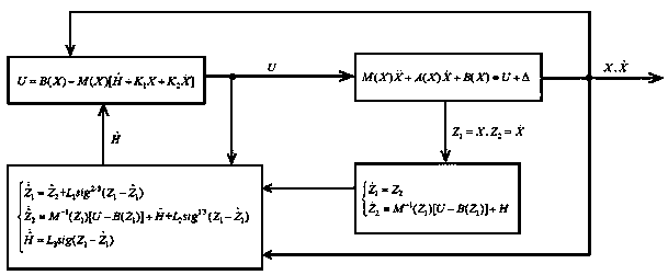
[0026] combine Figure 1 ~ Figure 3 The visual servo robot measurement lag compensation method provided by the present invention comprises the following steps:

[0027] Step 1: If figure 2 As shown, a camera is installed on the inner axis of the two-axis visual servo robot. The camera shoots the moving target in real time, and extracts the eigenvalues ​​of the moving target from the image captured by the camera. The two-axis visual servo robot controller generates the angular velocity of the two axes of the robot according to the eigenvalues. Encoders are installed on the inner and outer axes of the robot to obtain angular velocity information. The two-axis visual servo robot includes the...


PUM


Abstract

The invention discloses a visual servo robot measurement time-delay compensation method. According to the method, the measurement time delay of a visual servo robot is compensated, the interference and a difference thereof in a system are estimated by utilizing an estimator. The state and the interference at current moment are predicted by combining with measurement output, and a composite controller is designed by utilizing feedback linearization. The composite controller feeds back the predicated value to the visual servo robot so as to guide the robot to work. According to the visual servorobot measurement time-delay compensation method provided by the invention, the stability degree of the system is improved, the feedback gain of the system is increased, and the dynamic response speedis improved, so that a servo control performance of the robot is remarkably improved.

Description

technical field [0001] The invention relates to a measurement time-lag compensation method for a visual servo robot, and belongs to the technical field of high-performance control of a visual servo robot. Background technique [0002] Visual servo robot is an important part of the robot field, and has a wide range of applications in the fields of automated production, modern logistics, national defense police and aerospace. Visual servo robot control can be divided into position-based and image-based visual servo control according to the way the image signal is utilized. Position-based visual servo control requires three-dimensional reconstruction, which depends on the calibration accuracy of the camera, and needs to be re-calibrated after changing the environment. The image-based visual servo control defines the error directly on the image plane, avoids the calibration problem, and has better robustness to environmental changes and camera parameter perturbations. [0003]...

Claims


Application Information

Patent Timeline
Patent Type & Authority Applications(China)
IPC IPC(8): B25J9/16
CPCB25J9/1628B25J9/1653
Inventor 徐龙
Owner 南京隆越自动化科技有限公司
Why Eureka
Try Eureka