Method for constituting modular lamp box

A light box and box technology, which is applied in the directions of illuminated signs, instruments, display devices, etc., can solve the problems of dark shadows in the box and the inability to realize shadowless splicing, etc., and achieve easy installation and maintenance, simple structure, and uniform light emission Effect

Inactive Publication Date: 2019-08-20
方迪勇
View PDF7 Cites 0 Cited by
  • Summary
  • Abstract
  • Description
  • Claims
  • Application Information

AI Technical Summary

Problems solved by technology

[0003] For light boxes in the field of advertising communication, there are mainly two structures: one is a light box with a side-entry backlight structure, which is mainly composed of a light guide plate and a light source. The light source is installed on the side of the light guide plate and at the bottom of the light guide plate There are engraved or printed light guide points. Due to the limitation of light guide distance, the light box with side-type backlight structure is suitable for products with a small light-emitting area, such as small-sized decorative paintings, window displays, flat panel lighting, etc. However, There are light sources on both sides or around the light guide plate, so that there are dark areas caused by the light source body on both sides or around the light guide plate, and shadowless splicing cannot be realized
The other is a light box with a direct backlight structure, which is mainly composed of a panel, a light source and a box body. The panel is installed on the front side of the box body, and the

Method used


Image

  • Method for constituting modular lamp box
  • Method for constituting modular lamp box
  • Method for constituting modular lamp box

Examples


Embodiment Construction

[0040] The technical solution in the embodiment of the present invention will be clearly and completely described below in combination with the accompanying drawings in the embodiment of a method for constructing a modular light box of the present invention.

[0041] The front side and the rear side described in the embodiments of the present invention are based on the directions shown in the description of the drawings.

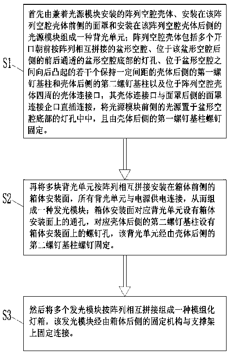
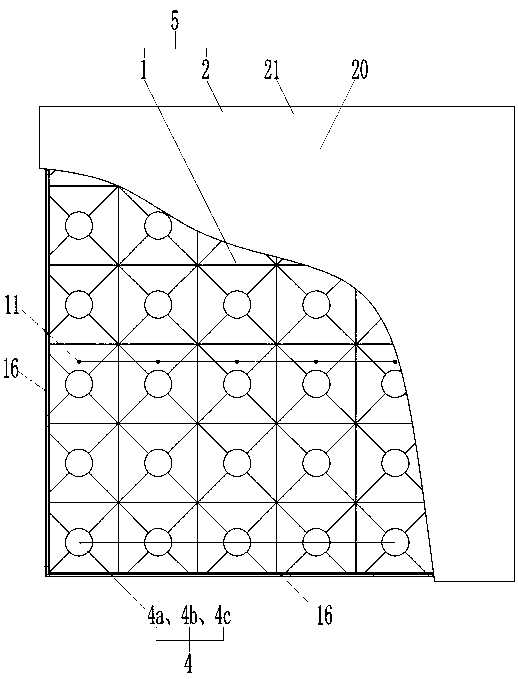
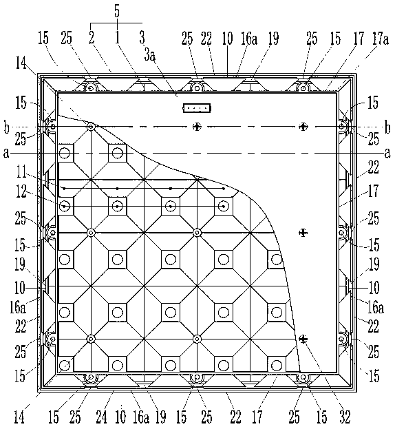
[0042] An embodiment of the method for forming a modular light box of the present invention, please refer to the attached figure 1 . First, if Figure 2 to Figure 9 As shown, an array cavity housing 1 installed with a light source module, a mask 2 installed on the front side of the array cavity housing 1, and a light source module 3 installed on the rear side of the array cavity housing 1 form a The backlight unit 5, wherein the array cavity housing 1 includes a plurality of basin-shaped cavities 11 with openings facing forward and splicing with each other...


PUM


Abstract

The invention relates to a method for constituting a modular lamp box. The method comprises the steps of: firstly, backlight units are each composed of an array cavity shell, a surface cover and a light source module, wherein the array cavity shell and the light source module are mounted together, the surface cover is mounted on the front side of the array cavity shell, and the light source moduleis mounted on the rear side of the array cavity shell; shell connecting openings and surface cover connecting rabbets in the rear sides of the surface covers are in straight-plugging connection, andlight sources on the front sides of the light source modules are arranged in lamp holes in the bottoms of basin-shaped cavities; then the multiple backlight units are mounted on the box body mountingface on the front side of a box body in a mutually-spliced mode according to the array, all the backlight units are in power supply connection with a power source, and thus light emitting modules areformed; and then the multiple light emitting modules are mutually spliced according to the array to form the modular lamp box. The modular lamp boxes of various specifications can be spliced accordingto the method, and have the advantages of uniform light emitting, simple structure, and convenient mounting and maintenance.

Description

technical field [0001] The invention relates to the field of light boxes, in particular to a method for forming a modular light box. Background technique [0002] As we all know, light boxes have a wide range of applications, which involve construction, industry, lighting, civil, commercial, medical, advertising, transportation and other special purposes. Among them, the application in the field of advertising communication is the most widely used, mainly including panel light boxes, cloth light boxes, crystal ultra-thin light boxes and plastic ultra-thin light boxes, mirror induction ultra-thin light boxes, magnetic suction ultra-thin light boxes, dynamic light boxes, etc. [0003] For light boxes in the field of advertising communication, there are mainly two structures: one is a light box with a side-entry backlight structure, which is mainly composed of a light guide plate and a light source. The light source is installed on the side of the light guide plate and at the b...

Claims


Application Information

Patent Timeline
IPC IPC(8): G09F13/04
CPCG09F13/04G09F13/0409G09F13/0413G09F13/0418
Inventor 方迪勇
Owner 方迪勇
Why Eureka
Try Eureka