[0016] The technical solutions in the embodiments of the present invention will be clearly and completely described below with reference to the accompanying drawings in the embodiments of the present invention. Obviously, the described embodiments are only a part of the embodiments of the present invention, but not all of the embodiments. Based on the embodiments of the present invention, all other embodiments obtained by those of ordinary skill in the art without creative efforts shall fall within the protection scope of the present invention.
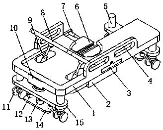
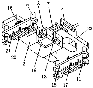
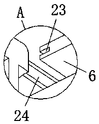
[0017] see Figure 1-3 , the present invention provides a technical solution: an ICU nursing bed for self-care of patients with damaged lower limbs, comprising a bed body 1, the upper side of the bed body 1 is provided with two sets of guardrails 4 symmetrically distributed, and one side of the bed body 1 is provided with two sets of guardrails 4 symmetrically distributed. A control switch 10 is provided, and four groups of upright columns 5 are arranged on the lower side of the bed body 1, which are equally spaced and symmetrically distributed. A connecting plate 15 is arranged in the middle position, and an adjusting bolt 17 is arranged in the middle position of the connecting plate 15. The upper end of the adjusting bolt 17 is connected with the runner 16, and the lower end of the adjusting bolt 17 is connected with the supporting plate 14, which is used to adjust the bed 1 The support separates the universal wheel 11 from the ground slightly to prevent movement. The side of the support plate 14 close to the adjusting bolt 17 is provided with a second pillar 13, the second pillar 13 is threadedly connected with the adjusting bolt 17, and the connecting plate 15 is close to the support plate. One side of the 14 is connected with one end of two sets of sliding shafts 21, the other end of the sliding shaft 21 is connected with the supporting plate 14 through the first column 12 provided at the corresponding position of the supporting plate 14, and the side of the bed body 1 close to the guardrail 4 passes through. The back support turning plate 8 is connected with the hinge, the lower part of the bed body 1 is provided with a supporting boss 22 on the side close to the back supporting turning plate 8, and the upper side of the supporting boss 22 is provided with a through slot, and the inner bottom surface of the through slot passes through the ten thousand One end of the second electric telescopic rod 9 is connected to the joint, the other end of the second electric telescopic rod 9 is connected to the back support rotating plate 8 through a universal joint, and the output end of the control switch 10 is electrically connected to the input of the second electric telescopic rod 9 In the middle of the lower side of the bed body 1, there is a placing box 2, and the side of the bed body 1 close to the placing box 2 is provided with a urinal slot. 6 distribution is connected by the sealing groove 23 and the sealing plate 24 provided on the corresponding side for sealing and preventing the odor from escaping. The side of the board 3 close to the slide plate 6 is connected with one end of two sets of first electric telescopic rods 7 , the other end of the first electric telescopic rod 7 is connected with the slide plate 6 , and the output end of the control switch 10 is electrically connected to the first electric telescopic rod 7 . There is a feces box 19 in the middle of the placing box 2 for storing feces, the side of the placing box 2 close to the feces box 19 is provided with a chute, and the side of the feces box 19 away from the placing box 2 is provided with a handle 18.
[0018] The manner of controlling the first electric telescopic rod 7 and the second electric telescopic rod 9 by the control switch 10 adopts the prior art.
[0019] When in use: firstly, the second electric telescopic rod 9 can be controlled to open by the control switch 10, and the second electric telescopic rod 9 can telescopically push the connected back support plate 8 to rotate, so as to support the back of the patient. The provided universal wheel 11 moves the position, and then by rotating the runner 16, the runner 16 rotates to drive the adjustment bolt 17 to rotate, and the adjustment bolt 17 rotates to drive the threaded second column 13 to move, so that the support plate 14 is in contact with the ground. , to prevent movement, when the patient defecates, the first electric telescopic rod 7 can be controlled to open through the control switch 10, and the first electric telescopic rod 7 telescopically pushes the connected slide plate 6 to move to both sides, so as to facilitate the patient to take care of himself, and then use the handle 18 to remove the stool. The box 19 can be taken out from the storage box 2 for cleaning.
[0020] In the present invention, the universal wheel 11 provided at one end of the upright column 5 and the anti-skid pad 20 provided on the lower side of the support plate 14 are used to facilitate the movement and fixation of the bed, and the back support rotary plate 8 can provide back support for the patient conveniently. The provided fecal box 19 is convenient for the patient to take care of excretion and self-care, and the sealing groove 23 and the sealing plate 24 can be used together to prevent odor.
[0021] Although embodiments of the present invention have been shown and described, it will be understood by those skilled in the art that various changes, modifications, and substitutions can be made in these embodiments without departing from the principle and spirit of the invention and modifications, the scope of the present invention is defined by the appended claims and their equivalents.