Machining clamp

A fixture and workpiece technology, applied in manufacturing tools, metal processing equipment, clamping and other directions, can solve the problems of easy damage to the appearance of the case, the case is prone to shaking, and the clamping is unstable, so as to achieve stable clamping without difficulty. The effect of falling off and reducing damage

Active Publication Date: 2019-08-23
GUANGDONG EVERWIN PRECISION TECH
View PDF5 Cites 6 Cited by
  • Summary
  • Abstract
  • Description
  • Claims
  • Application Information

AI Technical Summary

Problems solved by technology

However, this clamping method is easy to damage the appearance of the watch case,

Method used


Image

  • Machining clamp
  • Machining clamp
  • Machining clamp

Examples


Example Embodiment

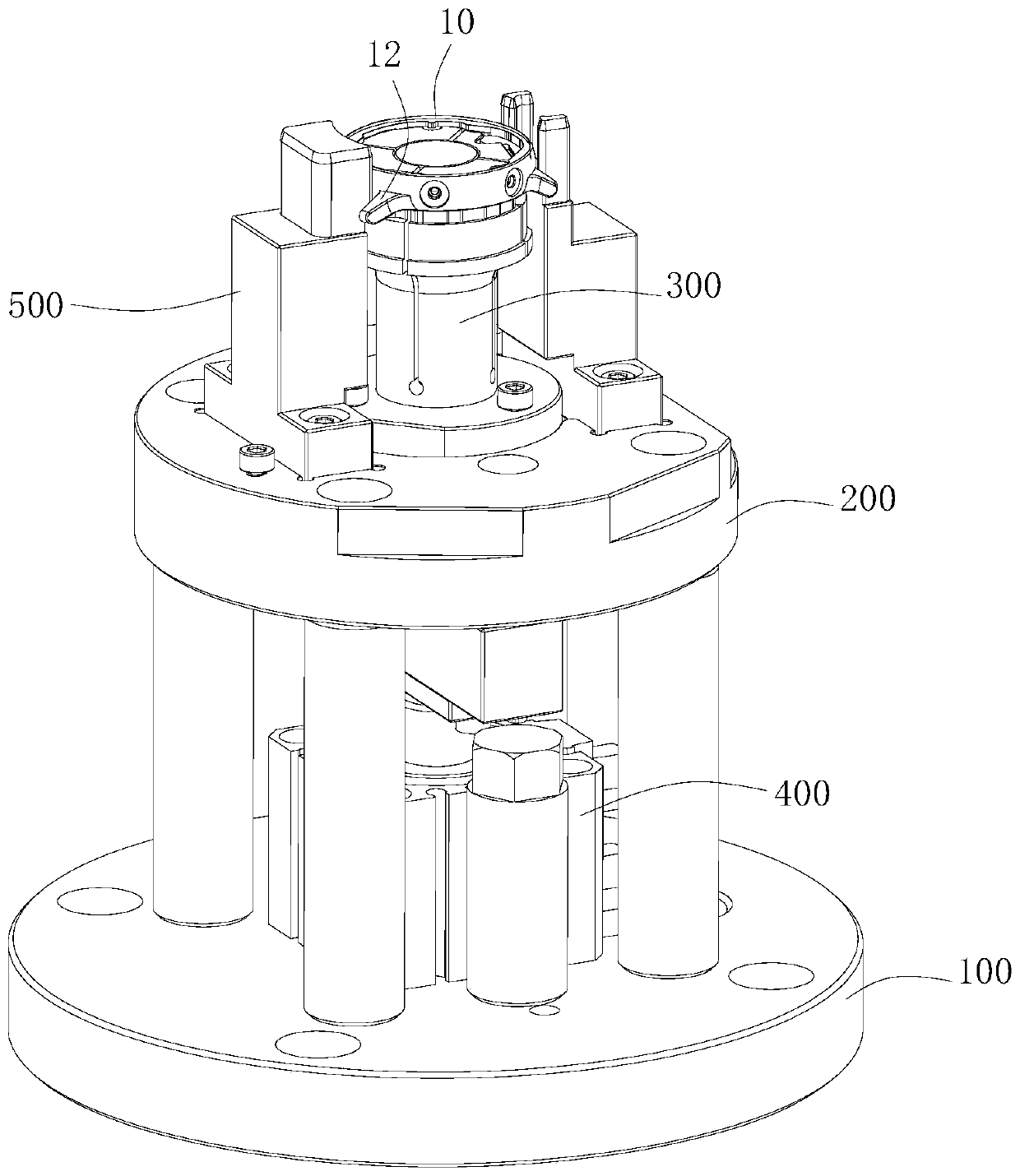
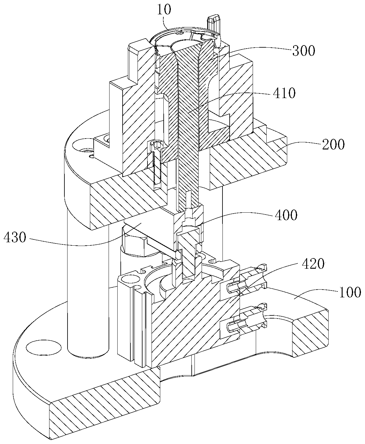
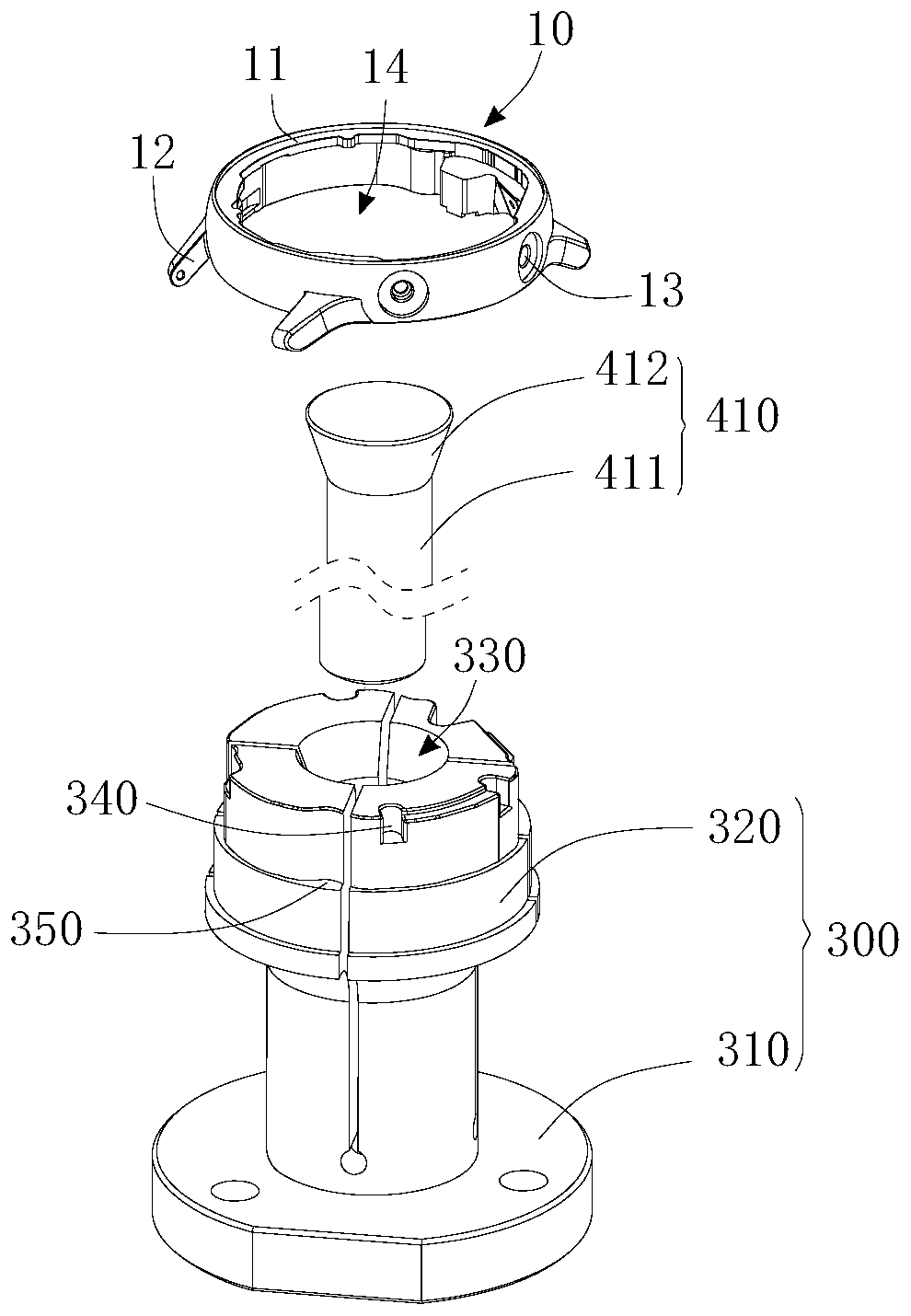
[0039] In order to facilitate the understanding of the present invention, the present invention will be described more fully below with reference to the relevant drawings. The preferred embodiments of the invention are shown in the drawings. However, the present invention can be implemented in many different forms and is not limited to the embodiments described herein. On the contrary, the purpose of providing these embodiments is to make the understanding of the disclosure of the present invention more thorough and comprehensive.

[0040] It should be noted that when an element is referred to as being "fixed to" another element, it can be directly on the other element or a central element may also exist. When an element is considered to be "connected" to another element, it can be directly connected to the other element or an intermediate element may be present at the same time. In contrast, when an element is referred to as being "directly on" another element, there are no in...


PUM


Abstract

The invention relates to a machining clamp for clamping a workpiece. The workpiece comprises a shell and an inner cavity formed in the shell. The inner wall of the inner cavity is in an irregular shape. The machining clamp comprises a base, a supporting table, a supporting nozzle and a drive assembly, the supporting table is arranged on the base, the supporting nozzle is arranged on the supportingtable and comprises a fixing piece and at least two supporting blocks arranged on the fixing piece, and a through hole is formed between the two supporting blocks. The drive assembly can be insertedin the through hole to drive at least two supporting blocks to expand so as to abut against the inner wall of the inner cavity of the workpiece. The faces, used for being attached to the inner wall ofthe inner cavity of the workpiece, of the supporting blocks correspond to the inner wall of the inner cavity so that profiling positioning can be formed. The profiling positioning manner is adopted,the workpiece can be prevented from rotating relative to the supporting nozzle, the supporting force, to the inner wall of the inner cavity, through the supporting nozzle is more uniform, and the supporting stability is improved.

Description

technical field [0001] The invention relates to the technical field of mechanical processing, in particular to a processing fixture. Background technique [0002] When the housing of an electronic product is machined, it usually needs to be clamped and positioned by a fixture, so that the housing of the electronic product can be processed more conveniently. [0003] At present, most watch cases adopt an integrated middle frame structure, and watch cases are usually provided with side holes. The traditional processing method is to clamp the lugs of the case with a clamp, and then process the side holes on the case. However, this clamping method is easy to damage the appearance of the watch case, and the clamping is unstable, so that the watch case is prone to shaking during processing. Contents of the invention [0004] Based on this, it is necessary to provide a processing fixture with firmer and more stable positioning for the above technical problems. [0005] A proces...

Claims


Application Information

Patent Timeline
IPC IPC(8): B23Q3/06
CPCB23Q3/062
Inventor 李荣辉梁梅新向春华王梓
Owner GUANGDONG EVERWIN PRECISION TECH
Why Eureka
Try Eureka