Numerical control machining center clamping mechanism and use method thereof

A technology of clamping mechanism and machining center, which is applied in the direction of metal processing, etc., can solve the problems of small range of clamping adaptation, low processing precision, small range, etc., and achieve the goal of increasing capacity, improving efficiency, and precise position Effect

Active Publication Date: 2020-05-08
正德职业技术学院
View PDF7 Cites 0 Cited by
  • Summary
  • Abstract
  • Description
  • Claims
  • Application Information

AI Technical Summary

Problems solved by technology

[0004] The object of the present invention is to solve the problem that the existing clamping mechanism can clamp the object with a small capacity; and the object is fixed at the clamped position of the clamping mechanism; the range of the object can be adjusted on the clamping mechanism Small; the clamping mechanism can only clamp and fix objects of the same width and size, and the range of clamping adaptation is small; the efficiency and precision of the objects being clamped and processed on the clamping mechanism are low, and the clamping mechanism The stability of the object clamping is poor; when the object is clamped on the mechanism, the area that can be processed and covered is too small, resulting in the incomplete and fine processing of the object, which seriously affects the quality of the object being clamped. Clamping mechanism and working method of CNC machining center

Method used


Image

  • Numerical control machining center clamping mechanism and use method thereof
  • Numerical control machining center clamping mechanism and use method thereof
  • Numerical control machining center clamping mechanism and use method thereof

Examples


Embodiment Construction

[0035] The technical solutions of the present invention will be clearly and completely described below in conjunction with the embodiments. Apparently, the described embodiments are only some of the embodiments of the present invention, not all of them. Based on the embodiments of the present invention, all other embodiments obtained by persons of ordinary skill in the art without creative efforts fall within the protection scope of the present invention.

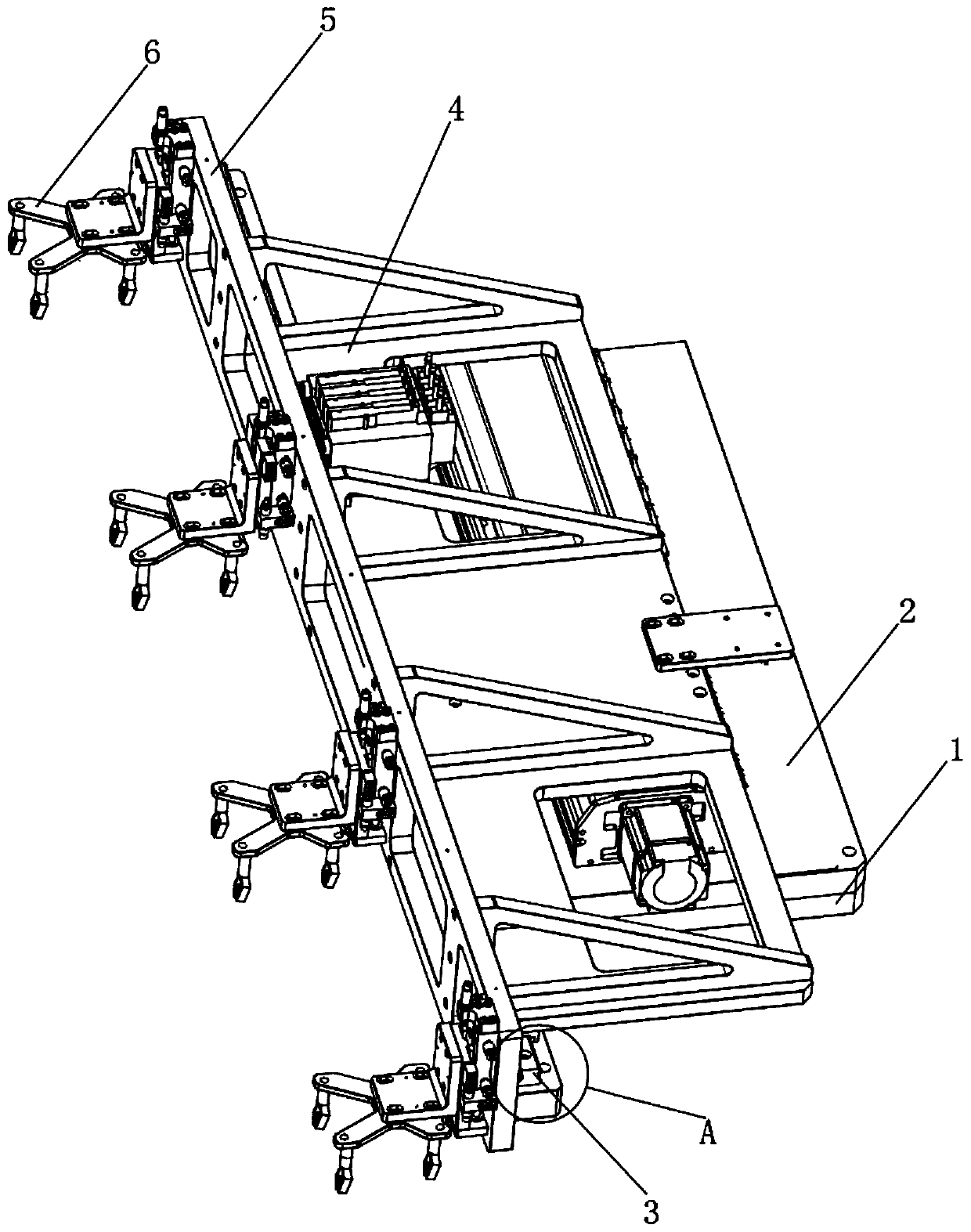
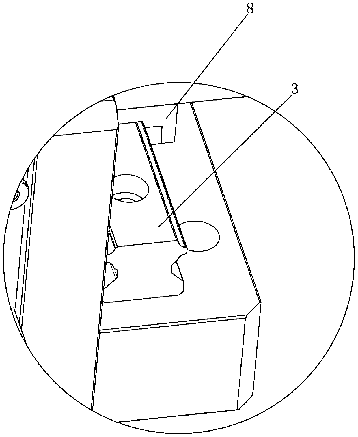
[0036] see Figure 1-10 As shown, a clamping mechanism of a CNC machining center includes a cuboid-shaped motor-1, a horizontally arranged rotary plate 2 and several clamping seats 6, the rotary plate 2 is a cuboid-shaped structure, and the motor-1 is passed through a gear One 7 is rotatably connected with the rotary plate 2, the upper end of the rotary plate 2 is provided with a rolling clamp rail 3, and the upper end of the rolling clamp rail 3 is provided with an inverted "U"-shaped sliding frame 8, and the upper part of t...


PUM


Abstract

The invention discloses a numerical control machining center clamping mechanism and a use method thereof. The numerical control machining center clamping mechanism comprises a first motor of a cuboidstructure, a horizontal rotating plate and a plurality of clamping bases. The rotating plate is of a cuboid structure. The upper side of the first motor is rotationally connected with the rotating plate through a first gear. The numerical control machining center clamping mechanism has the advantages that a second motor sleeving a slide frame drives a second gear to roll on the side wall of a rolling and clamping rail so as to drive a moving and mounting plate and a clamping and carrying base to move, so that the machined position of a clamped object is adjusted forwards and backwards, it is ensured that the object is more flexible and adjustable when clamped on the mechanism, and the machining efficiency of the object clamped on the mechanism is improved; a sixth motor drives a swinging and clamping claw to turn and swing through a transmission shaft, it is ensured that the mechanism can clamp objects of different widths and sizes, and the clamping application range of the mechanism is enlarged; and through a plurality of pressing cushions arranged on the lower side of the swinging and clamping claw at equal intervals, the object is clamped and collected, and it is ensured that the object is more stably and firmly clamped on the mechanism.

Description

technical field [0001] The invention relates to a clamping mechanism, in particular to a numerically controlled machining center clamping mechanism and a method for using the clamping mechanism, which belong to the technical field of clamping mechanism applications. Background technique [0002] The clamping mechanism is indispensable when the CNC machining center processes the object. The object to be processed is clamped and fixed by the clamping mechanism, which facilitates the processing equipment of the CNC machining center to process the object and improves the efficiency of the object being processed. [0003] The existing clamping mechanism of the CNC machining center still has many deficiencies in use. The existing clamping mechanism can hold the object with a small capacity, and the object is fixed at the position where the clamping mechanism is clamped. The range of activities that can be adjusted by the object on the clamping mechanism is small, and the clamping ...

Claims


Application Information

Patent Timeline
Patent Type & Authority Applications(China)
IPC IPC(8): B23Q7/04
CPCB23Q7/04B23Q7/043B23Q7/048
Inventor 赵寿宽龚君
Owner 正德职业技术学院
Why Eureka
Try Eureka