
Lathe fixture

A lathe jig and jig technology, applied in the direction of clamping, manufacturing tools, supports, etc., can solve the problems of low pass rate, increase of unqualified products, difficult clamping, etc., to save labor costs, improve production efficiency, and meet positioning requirements Effect

Inactive Publication Date: 2018-12-04
苏州嘉迈德电子科技有限公司
View PDF5 Cites 0 Cited by
  • Summary
  • Abstract
  • Description
  • Claims
  • Application Information

AI Technical Summary

Problems solved by technology

At present, with the continuous improvement of the degree of mechanization, the application of lathes is becoming more and more frequent. When processing parts, it is often difficult to clamp due to the irregular shape of the parts, resulting in the deviation of positioning during processing, resulting in an increase in unqualified products, especially in When processing flat surfaces of pipes, due to the bending of the pipe body, ordinary fixtures are difficult to clamp, resulting in slow processing efficiency and low pass rate, which affects normal processing

Method used


Image

  • Lathe fixture
  • Lathe fixture

Examples


Embodiment Construction

[0013] The technical solutions of the present invention will be further elaborated below according to the drawings and in conjunction with the embodiments.

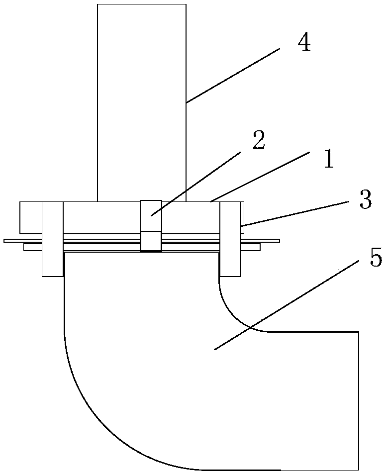
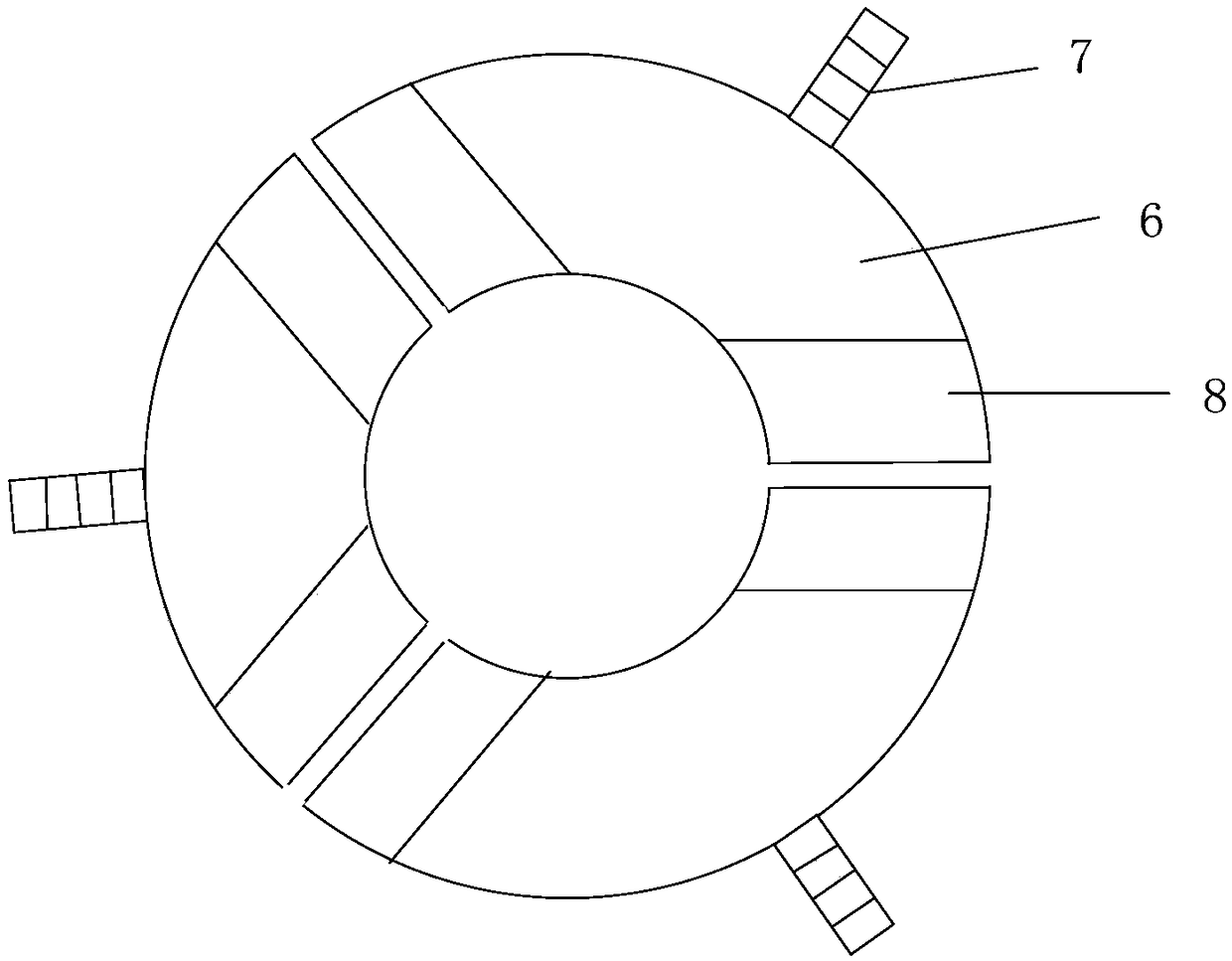
[0014] figure 1 It is a structural schematic diagram of the feeding fixture of the embodiment of the present invention, figure 2 It is a structural schematic diagram of a lathe fixture according to an embodiment of the present invention. A lathe fixture includes a feeding fixture and a processing fixture, wherein the feeding fixture includes a base 1, claws 2 and a limit rod 3, and the base 1 of the feeding fixture is connected to the feeding rod 4. The claw 2 is connected to the circumference of the base 1, and is used to fix the workpiece 5. The limit rod 3 is fixed on the circumference of the base 1; the processing fixture is a cylindrical structure as a whole, and the cylindrical structure is divided into three parts according to the circular axis The clamp 6 is obtained, the clamp 6 is connected with the lathe thr...


PUM


Abstract

The invention discloses a lathe fixture. The lathe fixture comprises a conveying fixture and a machining fixture. The conveying fixture comprises a base, clamping jaws and a limiting rod. The base ofthe conveying fixture is connected with a conveying rod, the clamping jaws are connected to the circumference of the base and used for fixing a workpiece, and the limiting rod is fixed to the circumference of the base; the machining fixture is overall of a cylindrical structure, the cylindrical structure is equally divided into three parts in the axial direction of the round shape, and thus a fixture body is obtained; and the fixture body is connected with a lathe through lathe chuck gripping jaws, and grooves are formed in the fixture body in the diameter direction and used for storing non-clamping parts of the workpiece. According to the lathe fixture, stable clamping is achieved, and the technical problem that irregular workpieces are hard to fix is solved; the structure is simple, theirregular pieces such as pipelines can be stably clamped, the positioning demand during product machining can be met, and the qualification rate of workpiece machining is increased; and the lathe fixture does not need to be operated manually, the workpiece is directly conveyed onto the machining fixture to be fixed through the conveying fixture, the labor cost is saved, and the production efficiency is improved significantly.

Description

technical field [0001] The invention belongs to the technical field of lathe processing, and in particular relates to a lathe clamp. Background technique [0002] Fixtures are devices used to fix the position of parts for turning and milling in the process of mechanical manufacturing. The fixtures used on lathes for processing objects are lathe fixtures. At present, with the continuous improvement of the degree of mechanization, the application of lathes is becoming more and more frequent. When processing parts, it is often difficult to clamp due to the irregular shape of the parts, resulting in the deviation of positioning during processing, resulting in an increase in unqualified products, especially in When processing flat surfaces of pipes, due to the bending of the pipe body, ordinary fixtures are difficult to clamp, resulting in slow processing efficiency and low pass rate, which affects normal processing. Contents of the invention [0003] In order to solve the abo...

Claims


Application Information

Patent Timeline
IPC IPC(8): B23Q3/12
Inventor 张军
Owner 苏州嘉迈德电子科技有限公司
Learn More