Image projection device and AR display equipment

A projection device and display device technology, applied in optical components, optics, instruments, etc., can solve the problems of large structural size of the optical system, limited limit resolution of the system, difficulty in improving the numerical aperture, etc., achieve small size, suppress stray light and the generation of ghost images, and the effect of reducing the difficulty of design

Pending Publication Date: 2019-08-23
BEIJING UNICORN TECH CO LTD
View PDF12 Cites 7 Cited by
  • Summary
  • Abstract
  • Description
  • Claims
  • Application Information

AI Technical Summary

Problems solved by technology

[0005] 1. There is a gap between the image source and the lens and the gap is too large, resulting in a large optical system structure size;
[0006] 2. There is air between the image source and the lens, the refractive index is low, the numerical aperture is difficult to increase, the limit resolution of the system is limited, and the design is difficult;
[0007] 3. Due to the large difference in refractive index between the air and the lens interface, the reflectivity of this surface is high, which is easy to cause ghost images and other stray light to the subsequent system;
[0008] 4. The distribution of components is scattered, which makes assembly and adjustment difficult and easy to damage

Method used


Image

  • Image projection device and AR display equipment
  • Image projection device and AR display equipment
  • Image projection device and AR display equipment

Examples


Embodiment 1

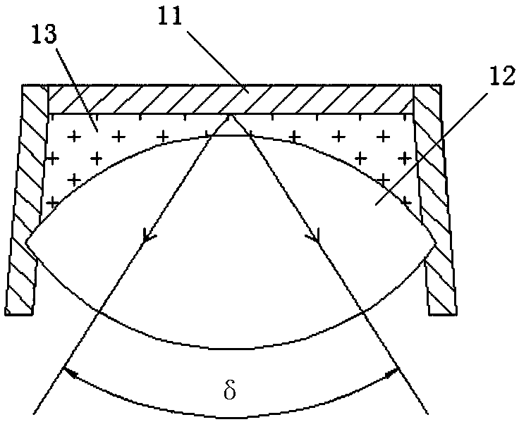
[0055] This embodiment provides an image projection device, which is applied to an AR display device. Such as figure 2 As shown, the image projection device includes an image source 11 and a lens assembly. The lens assembly is in close contact with the image source 11 . The lens assembly includes a matching mirror 13 and a lens 12 . It should be noted that the lens assembly may also only include matching mirrors.

[0056] Wherein, the function of the image source 11 is to display images that need to be projected into human eyes, and the image source 11 can be a planar image source, including but not limited to an image source with integrated light sources or a single image source. For example, OLED (Organic Light-Emitting Diode, organic light-emitting diode), LCOS (Liquid Crystal On Silicon, liquid crystal on silicon), LCD (Liquid Crystal Display, liquid crystal display), MEMS (Microelectromechanical Systems, micro-electromechanical display system), DMD (Digital Micro-mir...

Embodiment 2

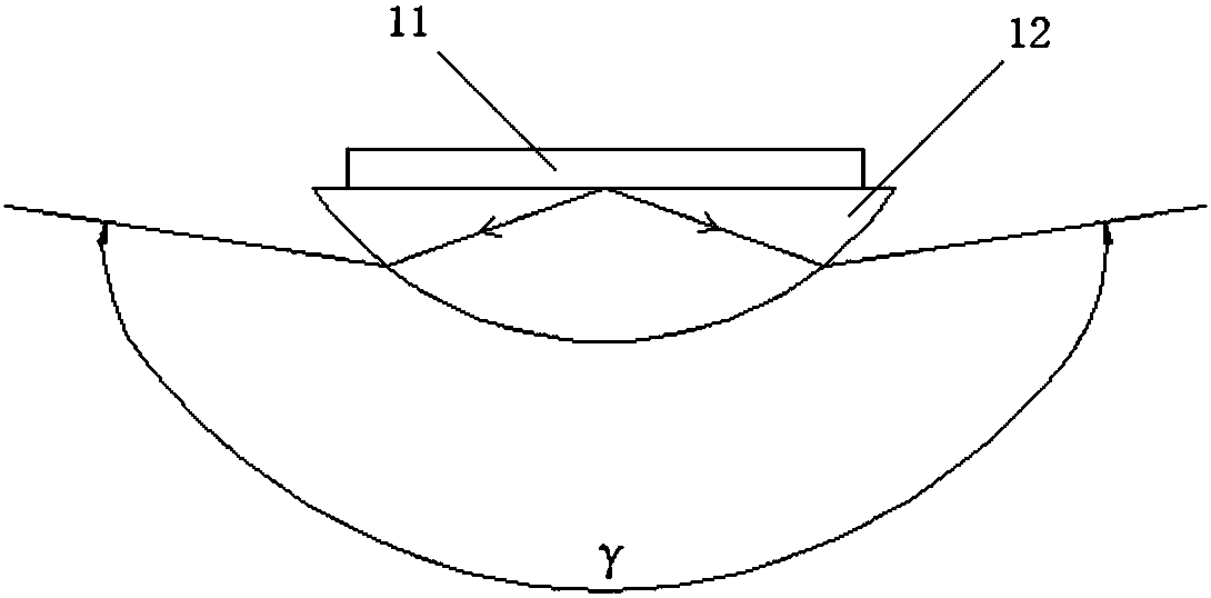
[0063] This embodiment provides another image projection device, which is applied to an AR display device. Such as image 3 As shown, the image projection device includes an image source 11 and a lens assembly. The lens assembly is in close contact with the image source 11 .

[0064] The lens assembly includes a lens 12 . The lens 12 may be a lens or a lens group composed of multiple lenses. Each lens in the lens or lens group can be a convex lens, a concave lens, or any combination of a convex lens and a concave lens. The image source 11 is closely attached to the lens 12 .

[0065] Since the image source 11 is closely attached to the lens 12, the image light emitted by the image source 11 will directly enter the lens 12, which reduces the refractive index difference at the interface when the light enters the lens, improves the transmittance of the upper surface of the lens, and increases the Light efficiency can also suppress the generation of stray light and ghost imag...

Embodiment 3

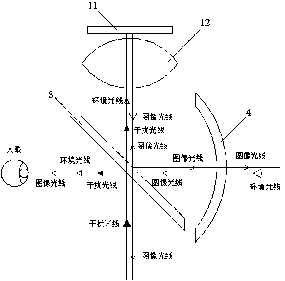
[0067] This embodiment provides an AR display device, such as Figure 4 As shown, the AR display device includes an image projection device 1 and a polarization optical path assembly.

[0068] Wherein, the image projection device 1 adopts the image projection device provided in Embodiment 1, including an image source 11 , a matching mirror 13 and a lens 12 . For its specific structure, reference may be made to Embodiment 1, which will not be repeated here.

[0069] The polarization optical path assembly includes a multi-layer film polarization beam splitter 5, a wave plate assembly 6 and a curved half mirror 4 arranged in sequence in the horizontal direction. The multilayer film polarizing beam splitter 5 is located below or above the image projection device 1 .

[0070] Such as Figure 5 As shown, the multilayer polarizing beam splitter 5 includes a substrate 51 , a polarizing film 52 and a polarizing beam splitting film 53 . The polarizing film 52 is used to pass the pol...


PUM


Abstract

The invention provides an image projection device and AR display equipment, and belongs to the technical field of augmented reality imaging. The image projection device includes an image source and alens assembly. The lens assembly tightly fits with the image source, refractive index difference of an interface when light enters a lens can be reduced, the transmittance of the upper surface of thelens can be enhanced, light efficiency can be increased, and the generation of stray light and ghost images can be inhibited. The advantages of the image projection device and AR display equipment areas follows: first, as the image source and the lens fit with each other or have no gaps, an optical system can be more compact in structure, smaller in volume, lighter in weight and comfortable in wearing; second, large numerical apertures can be realized by increasing image refractive indexes and using relatively small aperture angles, the deflection angles of marginal rays can be decreased, anddesign difficulties can be reduced; third, the refractive index difference at the interface of the lens can be decreased, the transmittance of the marginal rays can be enhanced, the ghost images canbe reduced, and brightness can be increased; and fourth, compact element arrangement, convenient installation and adjusting and high system intensity can be realized.

Description

technical field [0001] The present invention relates to the technical field of augmented reality imaging, and in particular, relates to an image projection device and an AR display device. Background technique [0002] AR (Augmented Reality, Augmented Reality) is also known as mixed reality. Its principle is to apply virtual information to the real world through computer technology. The real environment and virtual objects are superimposed on the same picture or space in real time. [0003] Currently, people can interact with the real world through wearable devices, such as AR glasses or AR helmets. Such as figure 1 A schematic structural diagram of an AR display device in an existing AR glasses or an AR helmet is shown, as shown in figure 1 As shown, the existing AR display device optical system includes an image source 11, a beam splitter 3, a curved half mirror 4 and a lens 12 located above the beam splitter 3, the image source 11 is arranged on the upper part of the op...

Claims


Application Information

Patent Timeline
Patent Type & Authority Applications(China)
IPC IPC(8): G02B27/01
CPCG02B27/0172G02B2027/011
Inventor 梁晓斌肖冰徐驰
Owner BEIJING UNICORN TECH CO LTD
Why Eureka
Try Eureka