A mechanical heating cup
A heating cup, mechanical technology, applied to drinking utensils and other directions, can solve the problems of inconvenient use, the heat preservation function cannot be heated at any time, and the water cup cannot be heated manually and mechanically. Effect
- Summary
- Abstract
- Description
- Claims
- Application Information
AI Technical Summary
Problems solved by technology
Method used
Image
Examples
Embodiment 1
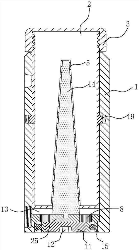
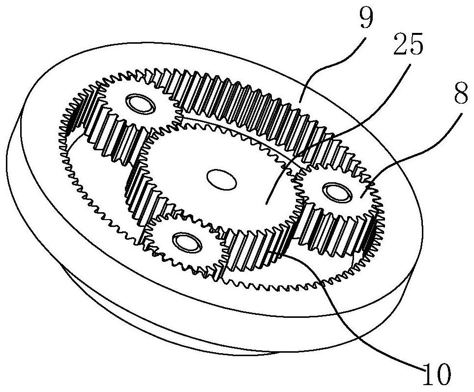
[0028] like figure 1 , figure 2 , image 3 and Figure 6 The shown mechanical heating cup includes a cup body 1, an inner tank cover 2, a cup cover 3 covering the inner tank cover 2, and a handle 4; the inner tank cover 2 is provided with a raised heat conduction sleeve 5 , the inside of the heat conduction sleeve 5 is a cavity 6, the cavity 6 is an opening 7 at the bottom of the cup body 1, and the bottom of the inner cavity of the cup body 1 is provided with a heating component, the heating component includes a heating element 25 and a planetary gear set, and the heating element 25 is in conflict with In the heat conduction sleeve 5, the planetary gear set includes a planetary gear 8 and a fixed gear ring 9, and a tooth groove 10 is arranged on the outer circumference of the heating element 25. One end is connected with a brake part 11, the brake part 11 is connected with the heating part 25, the brake part 11 can rotate around the heating part 25, the planetary gear 8 r...
Embodiment 2
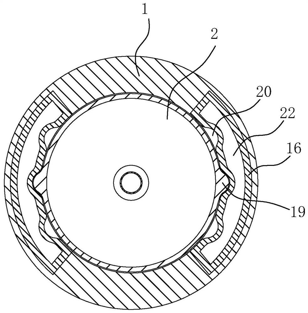
[0034] Such as Figure 4 , Figure 5 As shown, in this embodiment, on the basis of Embodiment 1, an elastic sheet is arranged between the inner wall of the cup body 1 and the liner sleeve 2, the elastic sheet includes a fixed part 16 and a deformation part 17, and the fixed part 16 is fixedly connected to the cup body 1. On the inner wall, a notch 18 is provided on the deformation portion 17, and a convex portion 19 is provided on the inner liner cover 2 to interfere with the notch 18. An installation opening 20 is provided on the elastic sheet, and the installation opening 20 is located on the side of the notch 18. The inner wall of the cup body 1 is provided with a traction port 21 that is flush with the installation port 20; during the installation process of the cup body 1 and the liner sleeve 2, the common method is a tight fit, which generally cannot be disassembled, and the two can be assembled after assembly. Eliminate looseness, and the commonly used materials for th...
Embodiment 3
[0037] Such as Figure 7-Figure 9 As shown, the design of this embodiment is based on implementation 1 or embodiment 2, the handle 4 is detachably connected with the cup body 1, one end of the handle 4 is connected with the positioning port 12, and the handle 4 drives the brake 11 to rotate, The other end of the handle 4 is a movable part. The movable part includes a stud 23 connected to the handle 4 and a screw sleeve 24 sleeved on the stud 23. The outer surface of the screw sleeve 24 is provided with threads, and the screw sleeve 24 is matched with the cup body 1. connection; when used as an operating handle, no other tools are required. By disassembling the handle 4 and inserting one end of the handle 4 into the positioning port 12, the brake part 11 can be driven to rotate and heat. The positioning port 12 and the end of the handle 4 can be designed as Polygons, such as quadrilaterals, pentagons, and hexagons, are easy to process and manufacture. The movable part and the h...
PUM
 Abstract
Description
Claims
Application Information
 - R&D
- Intellectual Property
- Life Sciences
- Materials
- Tech Scout
- Unparalleled Data Quality
- Higher Quality Content
- 60% Fewer Hallucinations
Browse by: Latest US Patents, China's latest patents, Technical Efficacy Thesaurus, Application Domain, Technology Topic, Popular Technical Reports.
© 2025 PatSnap. All rights reserved.Legal|Privacy policy|Modern Slavery Act Transparency Statement|Sitemap|About US| Contact US: help@patsnap.com


