Tilt frame adjustment mechanism

A technology of adjustment mechanism and tilting frame, which is applied in the field of plastic film production, can solve problems such as extrusion deformation of film bubbles and uneven thickness of film bubbles, achieve uniform thickness, convenient width adjustment, and improve film quality

Active Publication Date: 2021-05-28
CHONGQING RUITING PLASTIC
View PDF8 Cites 0 Cited by
  • Summary
  • Abstract
  • Description
  • Claims
  • Application Information

AI Technical Summary

Problems solved by technology

[0006] The present invention intends to provide a tilting frame adjustment mechanism to solve the problems in the prior art that the film bubble is easily deformed by the herringbone plate and the thickness of the film bubble is not uniform

Method used


Image

  • Tilt frame adjustment mechanism
  • Tilt frame adjustment mechanism
  • Tilt frame adjustment mechanism

Examples


Embodiment 1

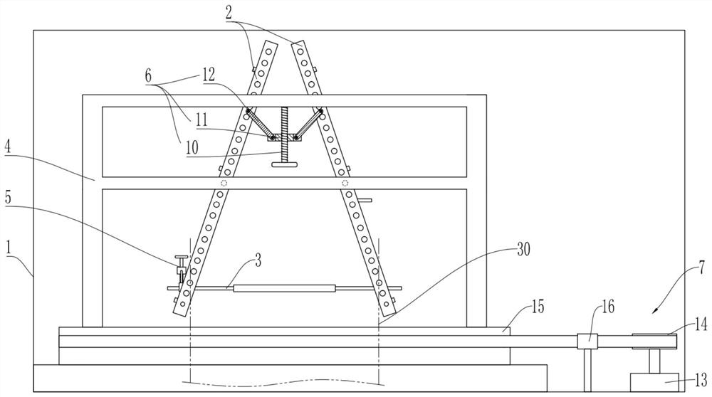
[0038] Embodiment one is basically as attached Figure 1 to Figure 3 Shown:

[0039] The tilting frame adjustment mechanism includes a frame 1, a herringbone plate, a limit roller 3, a support frame 4, a width adjustment assembly 5, an angle adjustment assembly 6 and a drive assembly 7 located on the frame 1. The herringbone plate includes two opposite The tilting frame 2, the limit roller 3 is located between the two tilting frames 2; the two tilting frames 2 and the supporting frame 4 are connected and rotated to be connected with a rotating shaft, the inclined frame 2 is suspended on the supporting frame 4 through the rotating shaft, and the drive assembly 7 Used to drive the support frame 4 to rotate.

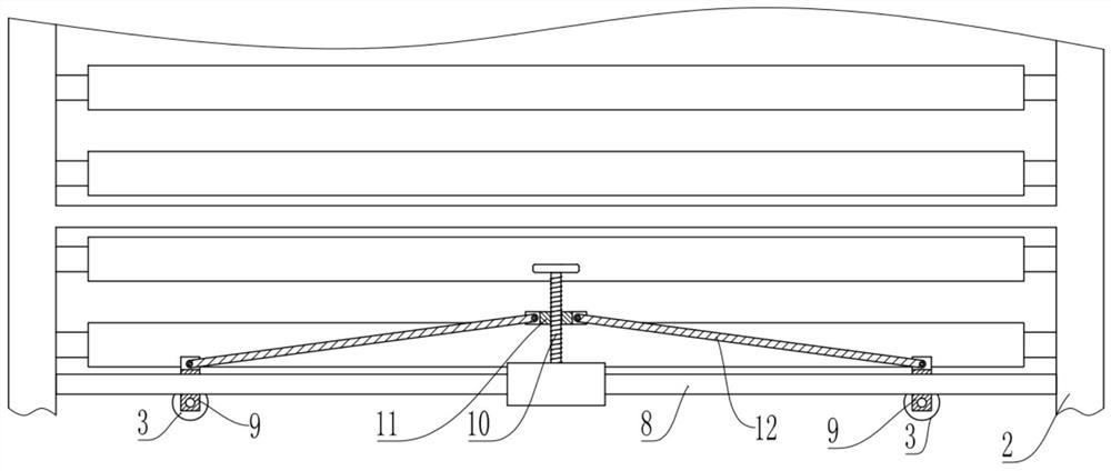
[0040] combine figure 2 , the two inclined frames 2 are provided with a horizontal slide bar 8, the slide bar 8 is provided with a slide block 9, and the slide block 9 slides laterally on the slide bar 8 through a bearing.

[0041] The left end of limit roller 3 is slid...

Embodiment 2

[0051] Embodiment two is basically as attached Figure 4 to Figure 6 Shown:

[0052] In Embodiment 2, a humidification assembly 17 is added on the basis of Embodiment 1. The humidification assembly 17 includes a rotating plate 18 and several humidification tubes 19 uniformly distributed along the circumference of the film bubble 30. Several humidification tubes 19 enclose the film bubble 30. The frame 1 A cover plate 20 is installed on the cover plate 20 through screws, the humidifying cylinder 19 is fixed on the cover plate 20 through screws, and the rotating plate 18 is connected with the turntable 15 through bolts.

[0053] to combine Figure 4 and Figure 5 The humidifying cylinder 19 is provided with a connecting rod 21 and a piston 22, the piston 22 is vertically slidably connected in the humidifying cylinder 19, the bottom end of the connecting rod 21 is fixedly connected with the piston 22, the top of the connecting rod 21 passes through the humidifying cylinder 19, ...


PUM


Abstract

The invention relates to the technical field of plastic film production, and specifically discloses a tilting frame adjustment mechanism, including a frame and a herringbone board. The drive assembly on the frame, the limit roller is located between two inclined frames, and the two inclined frames are equipped with slide bars, and the two ends of the limit roller are respectively slidably connected to the slide bars of the two inclined frames; the two inclined The frames are all connected to the support frame, and the drive assembly is used to drive the support frame to rotate; the width adjustment assembly is located between the two limit rollers, and the width adjustment assembly includes a guide rod, a sliding seat and two push rods, and the guide rod is rotatably connected to it On one slide bar, the slide seat is slidably connected to the guide rod, one ends of the two push rods are both rotatably connected to the slide seat, and the other ends of the two push rods are respectively rotatably connected to the two limit rollers. This solution is used to solve the problems in the prior art that the bubbles are easily squeezed and deformed by the herringbone plate and the thickness of the bubbles is not uniform.

Description

technical field [0001] The invention relates to the technical field of plastic film production, in particular to a tilting frame adjustment mechanism. Background technique [0002] In the process of film blow molding by flat extrusion top blowing method, the traction roller pulls the film bubble from the bottom to the top through the herringbone plate, the outer wall of the film bubble slides upwards close to the herringbone plate, and the film bubble is clamped by the herringbone plate The bottom is folded up, and then rolled into a flat film under the action of the traction roller. Most of the existing herringbone boards are composed of two inclined frames. The upper edges are close to each other to form a gap, and the lower edges are separated from each other. The cross-section forms a "herringbone" shape. The angle formed by the two inclined frames is fixed. Can not be adjusted, resulting in only applicable to a single film blowing machine, which is not conducive to pop...

Claims


Application Information

Patent Timeline
Patent Type & Authority Patents(China)
IPC IPC(8): B29C55/28
CPCB29C55/28
Inventor 曹玉毛潞
Owner CHONGQING RUITING PLASTIC
Why Eureka
Try Eureka