Airtight valve air tightness detection equipment

An air tightness detection and sealing valve technology, which is used in fluid tightness testing, liquid tightness measurement using liquid/vacuum degree, measuring device, etc., which can solve the inconvenience of removing the support rod 8, and placing and removing it repeatedly. The support rod process is cumbersome and other problems, to achieve the effect of simplifying the detection process and avoiding the offset in the vertical direction

Inactive Publication Date: 2019-08-30
北京鑫中昊科技股份有限公司
View PDF12 Cites 0 Cited by
  • Summary
  • Abstract
  • Description
  • Claims
  • Application Information

AI Technical Summary

Problems solved by technology

As a result, the process of repeatedly placing and removing the support rod 8 is cumbersome, and the pressure plate 3 presses the support rod 8 too tightly and is not easy to remove the support rod 8

Method used


Image

  • Airtight valve air tightness detection equipment
  • Airtight valve air tightness detection equipment
  • Airtight valve air tightness detection equipment

Examples


Embodiment 1

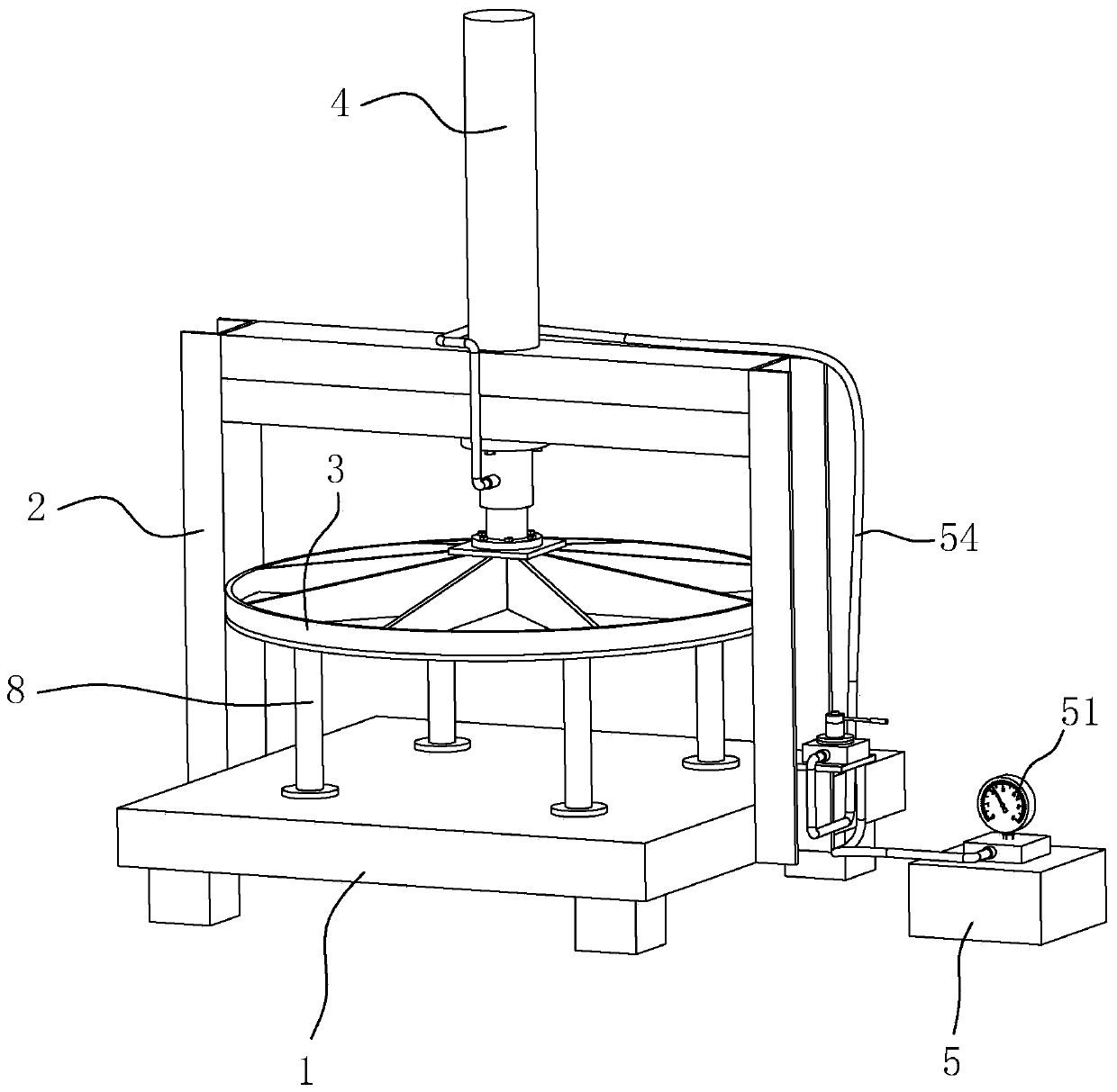
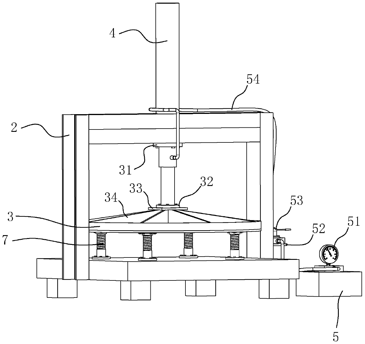
[0041] Embodiment one: refer to image 3 , is an airtightness testing device for a closed valve disclosed in the present invention, comprising a base 1 with a horizontal upper surface, a mounting frame 2 is welded on the base 1, a cylinder 4 is installed at the center of the mounting frame 2, and the piston rod of the cylinder 4 faces The bottom is set, the cylinder body of the cylinder 4 passes through the mounting frame 2, and its lower end is connected and fixed with the bottom bolt of the mounting frame 2 through the flange 31.

[0042] The lower end of the cylinder 4 piston rod is welded with a disc 32, the disc 32 is fixed with a square connecting plate 33 by bolts, the lower surface of the connecting plate 33 is fixed with a pressure plate 3, and the upper surface of the pressure plate 3 is welded with a vertical rib 34, the rib The plates 34 are distributed in a circular array with respect to the center of the pressure plate 3 , and the tops of the ribs 34 are welded t...

Embodiment 2

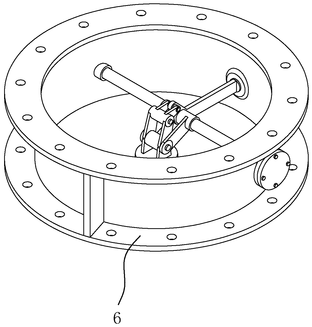
[0051] Embodiment 2: an airtightness detection device for a closed valve, which is different from Embodiment 1 in that, such as Figure 5 As shown, the interior of the support cylinder 71 in the support assembly 7 is hollow and a sliding cylinder 75 is slidably connected, as shown in Image 6 and Figure 7 As shown, the inner wall of the support cylinder 71 is provided with an axial sliding groove 751, and the outer wall of the sliding cylinder 75 is provided with a sliding block 752, which slides in the sliding groove 751 by sliding. The upper end of the sliding cylinder 75 is fixed with the base 1 by bolts, the lower end is welded with a spring 73, and the lower end of the spring 73 is welded and fixed with the bottom of the inner wall of the support cylinder 71. is compressed; when the pressure plate 3 rises after testing the airtight valve 6, the spring 73 recovers upwards, but is still in a slightly pressurized state, thereby providing an upward support force to the pres...


PUM


Abstract

The invention relates to airtight valve air tightness detection equipment, comprising a base and a pressure plate which is located above the base and is driven by an air cylinder. Supporting assemblies is connected between the base and the pressure plate, wherein the supporting assemblies are pressed to generate restoring force, thereby supporting the pressure plate. According to the equipment, aneffect of preventing supporting rods from being placed and taken down repeatedly is achieved, and the effect of simplifying an airtight valve detection process is also achieved.

Description

technical field [0001] The invention relates to the technical field of airtightness detection of airtight valves of civil air defense doors, in particular to airtightness detection equipment of airtight valves. Background technique [0002] In the civil air defense door, the airtight valve is a very important component. The airtightness of the airtight valve plays a vital role in the quality of the air defense door. Therefore, after the production of the airtight valve is completed, its airtightness needs to be tested to ensure Its quality is up to par. [0003] The Chinese patent with the existing notification number CN207502131U discloses a straight-through valve airtightness detection device, including a base, a valve mounting seat, a pressing mechanism and an air supply device. The valve mounting seat is an upper end opening and is vertically arranged on the The cylinder on the base, the pressing mechanism is arranged on the base to press the valve to be tested from the...

Claims


Application Information

Patent Timeline
IPC IPC(8): G01M3/28
CPCG01M3/2876
Inventor 李斌
Owner 北京鑫中昊科技股份有限公司
Why Eureka
Try Eureka