System and method for cooperatively detecting power equipment fault by ultraviolet and infrared imaging

A technology of infrared imaging and power equipment, applied in radiation pyrometry, measuring device, temperature recording method, etc., can solve the problem of cumbersome detection process, and achieve the effect of simplifying the detection process and improving the accuracy

Pending Publication Date: 2022-04-19
孙娟
View PDF0 Cites 0 Cited by
  • Summary
  • Abstract
  • Description
  • Claims
  • Application Information

AI Technical Summary

Problems solved by technology

[0005] The purpose of the present invention is to provide an ultraviolet and infrared imaging cooperative detection system for power equipment faults, which has the advantage of being able to automatically perform ultraviolet and infrared imaging detection on electric equipment, and solves the problem of cumbersome detection process caused by sequential use of infrared detection and ultraviolet detection

Method used


Image

  • System and method for cooperatively detecting power equipment fault by ultraviolet and infrared imaging
  • System and method for cooperatively detecting power equipment fault by ultraviolet and infrared imaging
  • System and method for cooperatively detecting power equipment fault by ultraviolet and infrared imaging

Examples


Embodiment 1

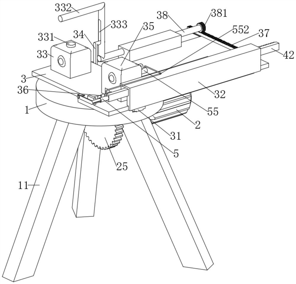
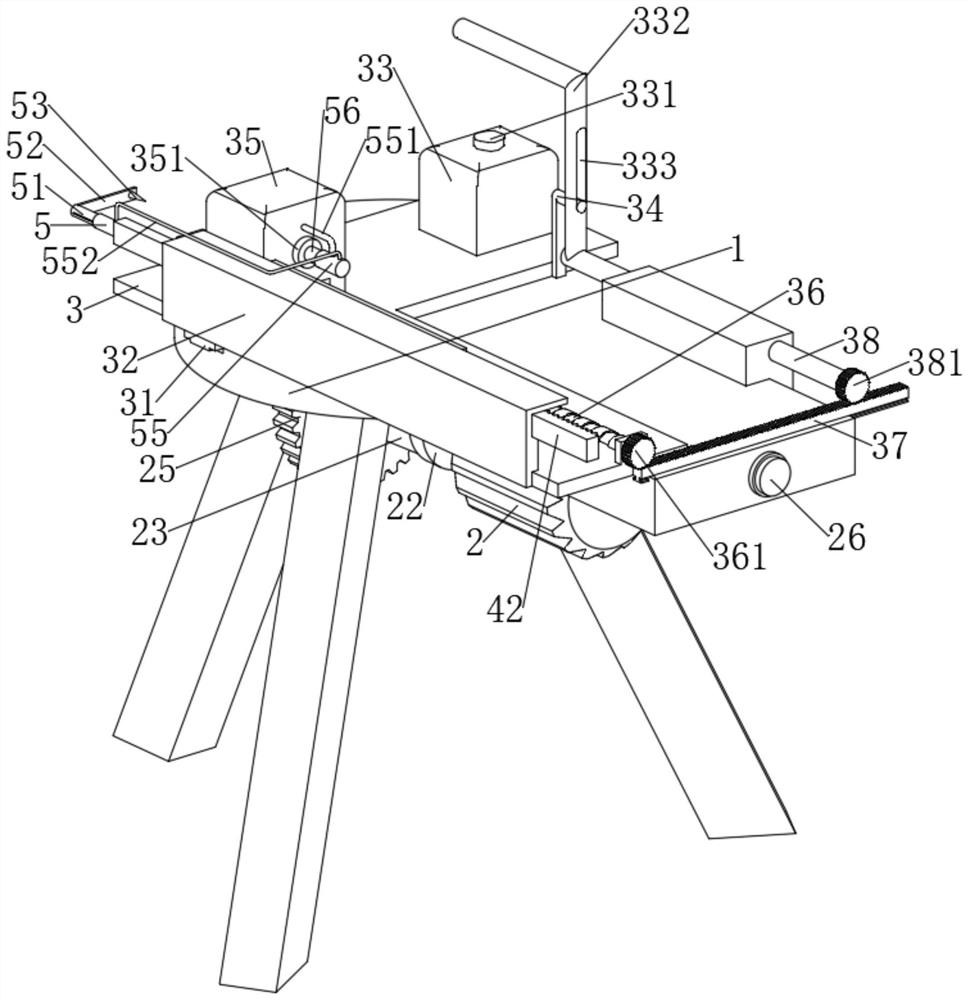
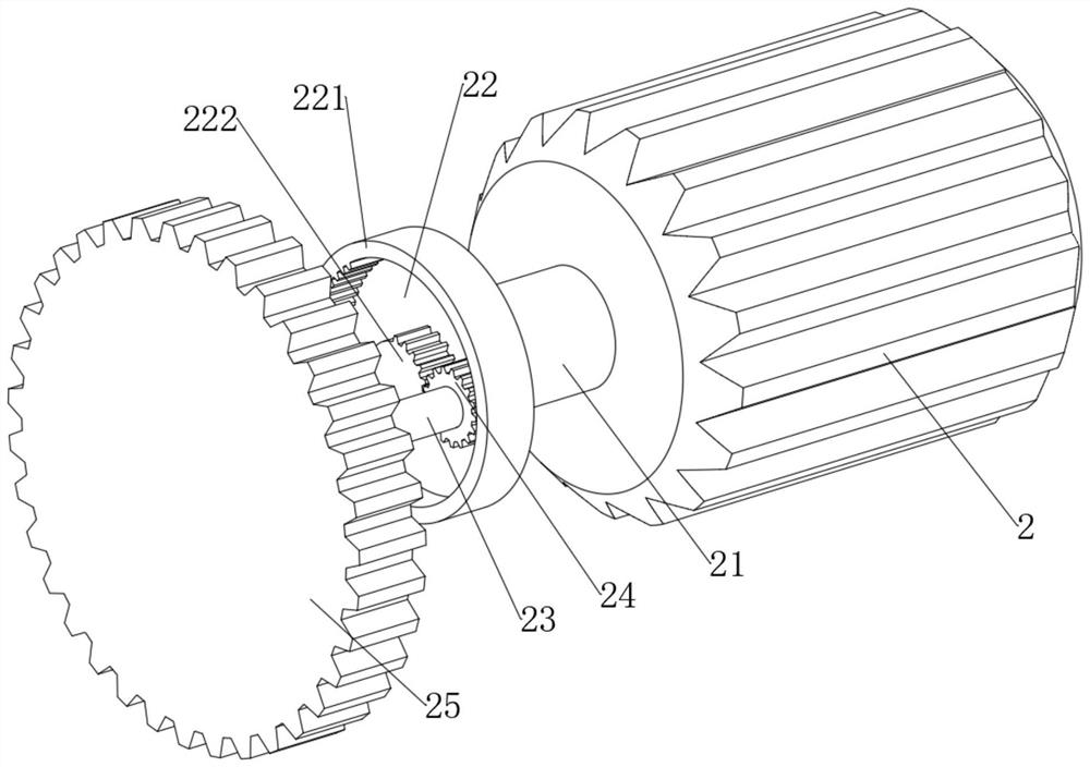
[0032]The present invention provides a technical solution: an ultraviolet and infrared imaging cooperative detection system for power equipment faults, including an infrared imager 33, an ultraviolet imager 35, a fixed plate 1, and a tripod 11 fixedly connected to the bottom of the fixed plate 1, sliding on the fixed plate 1 A mounting plate 3 is connected, the infrared imager 33 is fixedly connected to the mounting plate 3, the ultraviolet imager 35 is slidably connected to the mounting plate 3, and the mounting plate 1 is provided with a device for driving the mounting plate 3 to reciprocate axially on the mounting plate 1. The drive mechanism, the drive mechanism includes a motor 2 fixedly connected to the bottom surface of the fixed plate 1, the fixed plate 1 is provided with a switch 26 for controlling the start and stop of the motor 2, the output end of the motor 2 is fixedly connected with a drive shaft 21, the drive shaft 21 A disk 22 is fixedly connected to the top, an...

Embodiment 2

[0035] On the basis of Embodiment 1, furthermore, the driving mechanism is provided with a first shooting mechanism for making the infrared imager 33 shoot, and the first shooting mechanism includes an L-shaped driving lever 34 fixedly connected to the mounting plate 3, The fixed plate 1 is rotatably connected with an installation shaft 38, and the installation shaft 38 is fixedly connected with an L-shaped pressing bar 332. The L-shaped pressing bar 332 is provided with a chute 333 for the L-shaped driving lever 34 to slide. There is a first shutter key 331 for controlling the operation of the infrared imager 33 , and the L-shaped pressure bar 332 offsets against the first shutter key 331 intermittently.

[0036] refer to figure 1 , figure 2 and Figure 4 , when the infrared imager 33 on the mounting plate 3 moves to the middle of the fixed plate 1, the L-shaped driving lever 34 fixedly connected on the mounting plate 3 moves synchronously with the mounting plate 3, becaus...

Embodiment 3

[0040] On the basis of Embodiment 2, furthermore, the drainage mechanism is provided with a second shooting mechanism for making the ultraviolet imager 35 shoot, and the second shooting mechanism includes a third rack 37 slidably connected to the fixed plate 1, On the installation shaft 38, one end away from the L-shaped pressure bar 332 is coaxially fixedly connected with a third gear 381, the third gear 381 meshes with the third rack 37, the mounting plate 3 is connected with a screw 36 in rotation, and the bottom of the ultraviolet imager 35 A threaded hole is provided to cooperate with the screw rod 36 , and the end of the screw rod 36 away from the ultraviolet imager 35 is coaxially fixedly connected with a fourth gear 361 , and the fourth gear 361 meshes with the third rack 37 .

[0041] refer to figure 1 , figure 2 , Figure 4 and Figure 5 , because the mounting plate 3 axially reciprocates on the mounting plate 1, and then the infrared imager 33 and the ultraviole...


PUM


Abstract

The invention discloses an ultraviolet and infrared imaging cooperative detection power equipment fault system, and belongs to the field of power equipment detection.The ultraviolet and infrared imaging cooperative detection power equipment fault system comprises an infrared imager, an ultraviolet imager, a fixing plate and a tripod fixedly connected to the bottom of the fixing plate, and a mounting plate is slidably connected to the fixing plate; a driving mechanism for driving the mounting plate to axially slide on the fixing plate in a reciprocating manner is arranged on the fixing plate, the driving mechanism comprises a motor fixedly connected to the bottom surface of the fixing plate, a disc is fixedly connected to a driving shaft, and an incomplete gear ring and an incomplete gear are coaxially and fixedly connected to the disc. The infrared imager and the ultraviolet imager are arranged on the mounting plate together, and the mounting plate moves back and forth, so that the detection process of the power equipment is simplified, the accuracy of the detection result is improved, and the halo discharge phenomenon can be detected by arranging the drainage mechanism.

Description

technical field [0001] The invention relates to the technical field of electric equipment detection, in particular to an ultraviolet and infrared imaging cooperative detection system for electric equipment faults. Background technique [0002] Power equipment mainly includes power generation equipment and power supply equipment. Power generation equipment is mainly power plant boilers, steam turbines, gas turbines, water turbines, generators, transformers, etc. Power supply equipment is mainly transmission lines of various voltage levels, transformers, contactors, etc. There are many electrical equipment in the power system. According to their different roles in operation, they are usually divided into electrical primary equipment and electrical secondary equipment. Most of the power equipment in the power system adopts a planned maintenance system. Serious defects, such as frequent temporary maintenance, insufficient or excessive maintenance, and blind maintenance, etc., ma...

Claims


Application Information

Patent Timeline
IPC IPC(8): G01J5/02G01J5/48
CPCG01J5/02G01J5/48
Inventor 孙娟
Owner 孙娟
Why Eureka
Try Eureka