Electric connector

A technology for electrical connectors and joints, applied in the field of electrical connectors, can solve problems such as unformed specifications, and achieve the effects of reducing electrical length, reducing wavelength, and increasing frequency

Active Publication Date: 2019-08-30
DEYI PRECISION ELECTRONIC IND CO LTD PANYU
View PDF3 Cites 3 Cited by
  • Summary
  • Abstract
  • Description
  • Claims
  • Application Information

AI Technical Summary

Problems solved by technology

How to install conductive plastic, especially how to install conductive plastic in the PCI-E connector, so that the electrical connector can achieve satisfactory high-frequency performance, currently the industry has not formed a standard, and it is also a key research project of our company

Method used


Image

  • Electric connector
  • Electric connector
  • Electric connector

Examples


Embodiment Construction

[0052] In order to facilitate a better understanding of the purpose, structure, features, and effects of the present invention, the present invention will now be further described in conjunction with the accompanying drawings and specific embodiments.

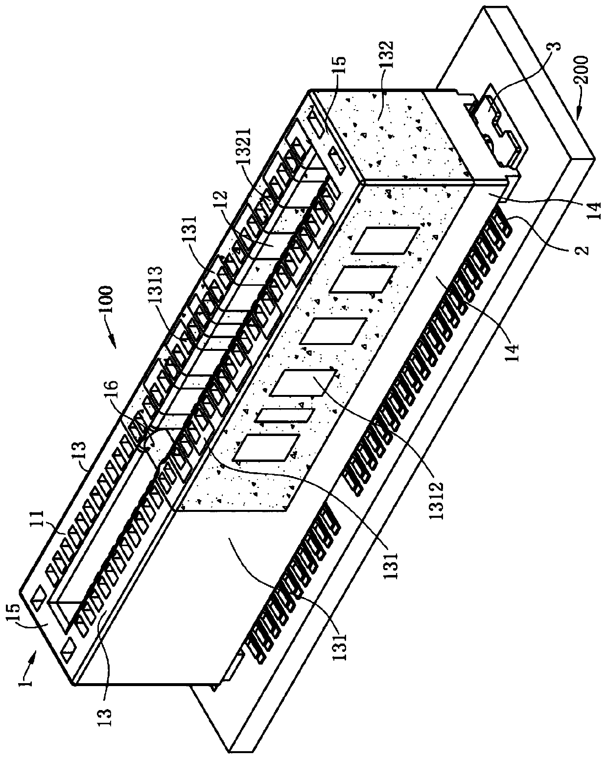
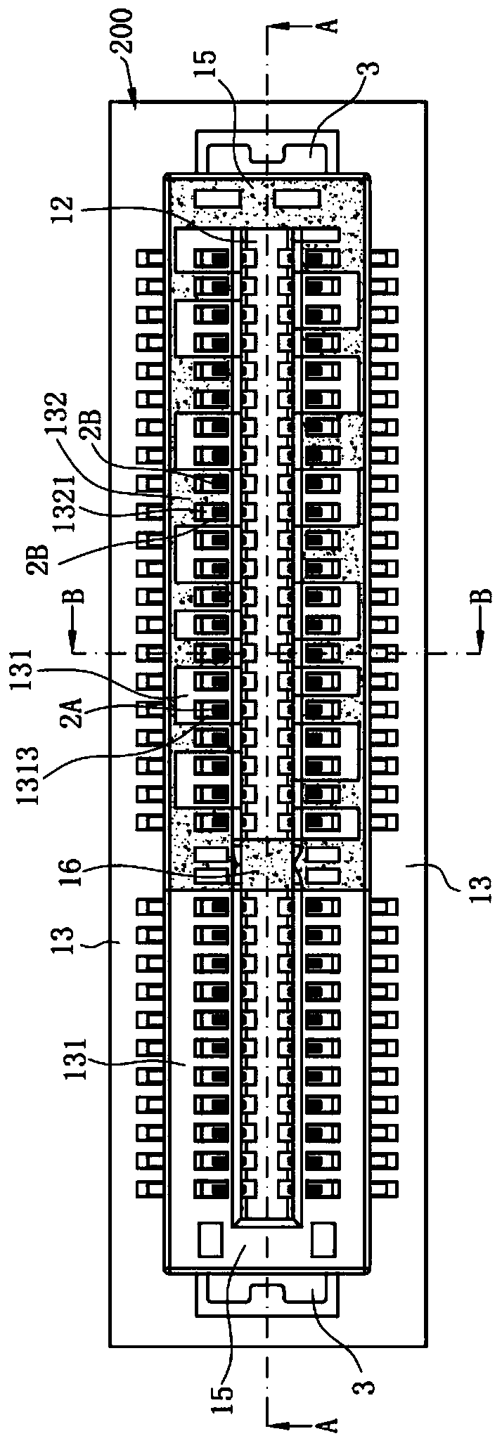
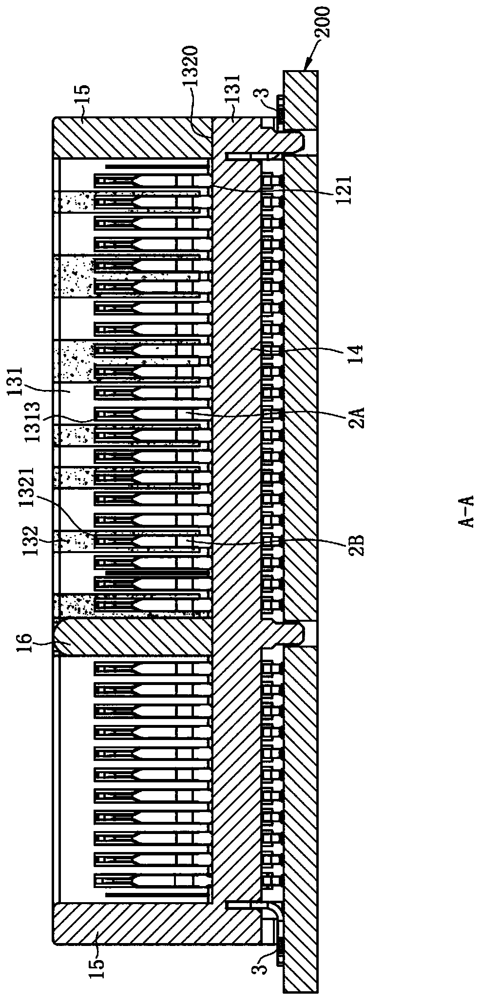
[0053] Such as figure 1 and figure 2 As shown, it is a preferred embodiment of the electrical connector 100 of the present invention, the electrical connector 100 is installed on a circuit board 200, and is used to insert a mating element (not shown), for example, the mating element for electronic cards. The electrical connector 100 includes a body 1 and a plurality of conductive terminals 2 mounted on the body 1, the body 1 is made of insulating plastic and conductive plastic, and the plurality of conductive terminals 2 include a plurality of signal terminals 2A As well as the plurality of ground terminals 2B, the structure and size of the signal terminal 2A and the ground terminal 2B are the same.

[0054] Such as figure...


PUM


Abstract

The invention discloses an electric connector, which comprises a body, a signal terminal and at least one grounding terminal, wherein the body is provided with a butting surface and sinks downward from the butting surface to form an inserting slot used for accommodating a butting element, the inserting slot is provided with a slot bottom surface, the body is provided with two side walls respectively located at two sides of the inserting slot, at least one side wall includes a first portion formed by insulation plastic and a second portion arranged on the first portion, the first portion is provided with a signal terminal hole, the second portion is made of conductive plastic and provided with a plurality of grounding terminal holes, the signal terminal hole and the grounding terminal holesare communicated with the inserting slot, and the grounding terminal holes at least partially exceed the slot bottom surface upward; the signal terminal is correspondingly accommodated in the signalterminal hole; the at least one grounding terminal is correspondingly accommodated in the at least one grounding terminal hole and connected with the second portion in a conductive manner; and both the signal terminal and the grounding terminal are provided with a contact portion, the contact portion protrudes into the inserting slot so as to be electrically connected with the butting element. Theelectrical length of the grounding terminal is changed through the second portion made of the conductive plastic to improve the high frequency performance.

Description

[0001] 【Technical field】 [0002] The invention relates to an electrical connector, especially an electrical connector suitable for transmitting high-frequency signals. [0003] 【Background technique】 [0004] With the development of technology and the upgrading of electronic components, the requirements for the frequency of signals transmitted by electrical connectors are getting higher and higher. For example, the PCI-E 5.0 specification under formulation expects the frequency of signals transmitted by electrical connectors to reach 32G, while transmission of high frequency One of the problems caused by the signal is that it is easy to generate high-frequency resonance, which is not conducive to signal transmission. In order to solve the above problems, the industry has tried to use conductive plastic to connect all the grounding terminals in the electrical connector, so as to improve the high-frequency performance of the electrical connector. The so-called conductive plasti...

Claims


Application Information

Patent Timeline
Patent Type & Authority Applications(China)
IPC IPC(8): H01R12/72H01R12/73H01R13/648H01R13/646H01R13/6581H01R13/6597H01R13/504H01R13/11H01R12/70
CPCH01R12/707H01R12/721H01R12/737H01R13/113H01R13/504H01R13/646H01R13/648H01R13/6581H01R13/6597
Inventor 张文昌殷佳旭
Owner DEYI PRECISION ELECTRONIC IND CO LTD PANYU
Why Eureka
Try Eureka