Machining method of umbrella-shaped valve disc

A processing method and technology for an umbrella valve, which are applied in the field of valve disc processing, can solve the problems that the valve disc is not easy to clamp, and it is difficult to ensure the coaxial accuracy of the upper and lower ends of the workpiece.

Active Publication Date: 2019-09-03
HARBIN TURBINE +1
View PDF9 Cites 1 Cited by
  • Summary
  • Abstract
  • Description
  • Claims
  • Application Information

AI Technical Summary

Problems solved by technology

[0003] The present invention solves the problem that it is difficult to clamp and ensure the coaxial accuracy of the upper and lower ends of the workpiece when processing the valve disc in the existing process scheme, and further provides a processing method for the umbrella-shaped valve disc

Method used


Image

  • Machining method of umbrella-shaped valve disc
  • Machining method of umbrella-shaped valve disc
  • Machining method of umbrella-shaped valve disc

Examples


specific Embodiment approach 1

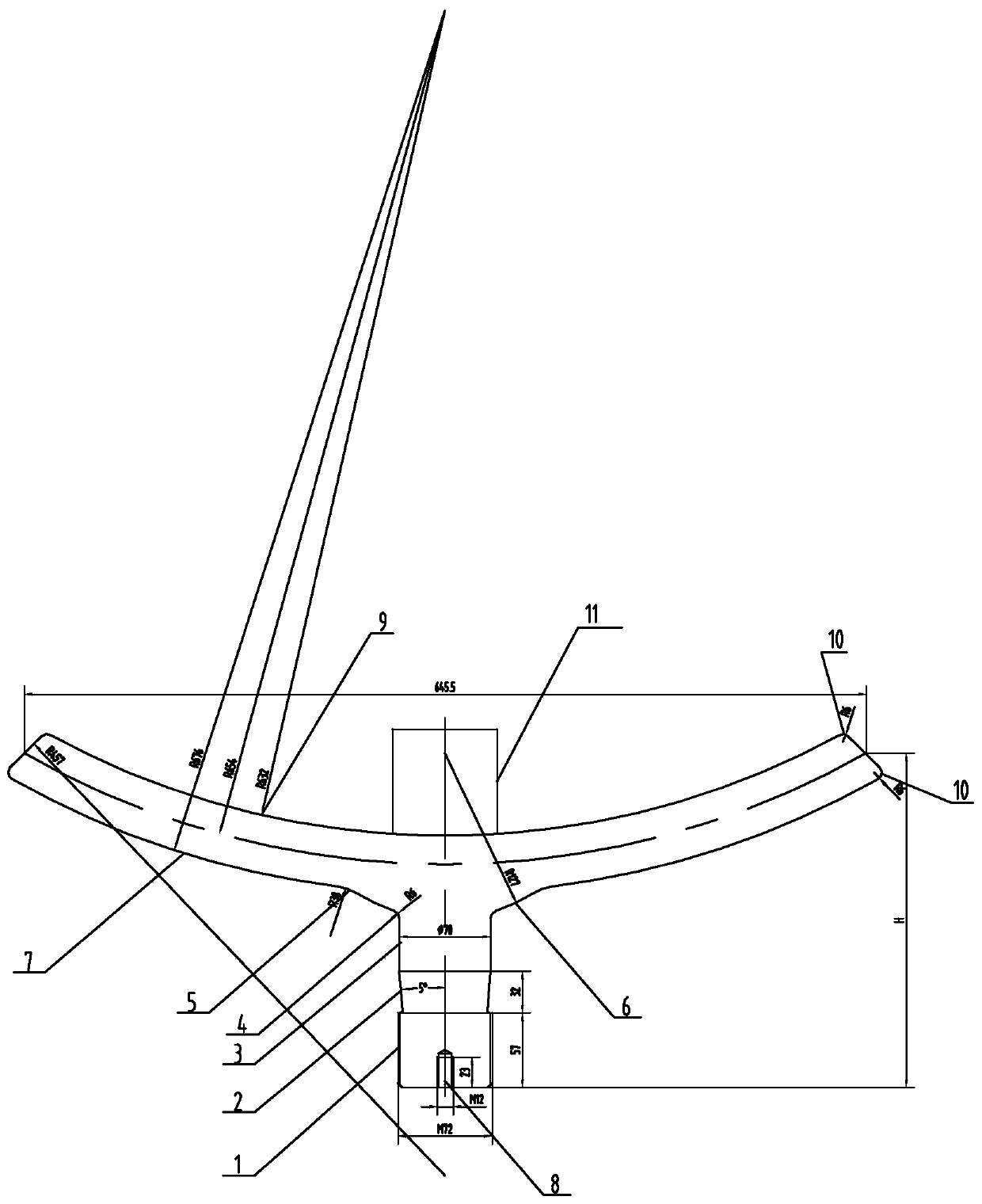
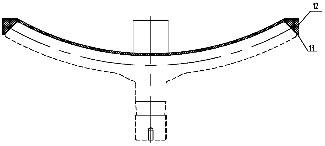
[0032] Specific implementation mode one: combine Figure 1 to Figure 3 To illustrate this embodiment, the processing method of the umbrella-shaped valve disc described in this embodiment is carried out in the following steps:

[0033] Step 1: preparing a blank and forging the blank;

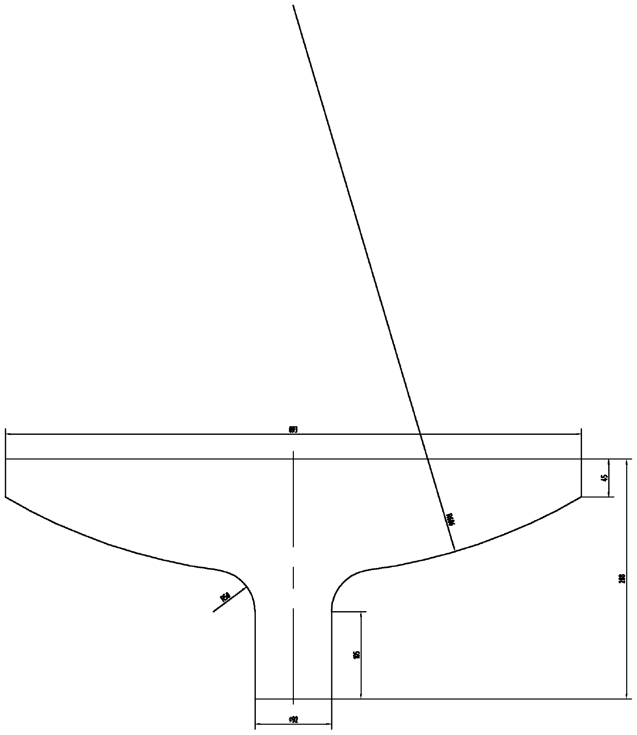
[0034] Step 2: select a horizontal lathe to rough turn the blank obtained in step 1, rough turn the outer circle and end face of the blank, and leave a clamping auxiliary head 11 at the center of the upper end of the workpiece;

[0035] Step 3: Tempering and stress-relieving the workpiece obtained after rough turning in Step 2;

[0036] Step 4: Select a horizontal lathe to turn each part of the lower end of the workpiece obtained in step 3;

[0037] Turning steps are as follows:

[0038] 1. Use the four-jaw chuck configured on the lathe to clamp the clamping auxiliary head reserved in the center of the upper end of the workpiece;

[0039] 2. Turn the threaded section 1 at the lower end of the...

specific Embodiment approach 2

[0050] Specific implementation mode two: combination Figure 1 to Figure 3 To illustrate this embodiment, the forging process described in Step 1 of this embodiment is: heating the forging to be processed to 1150°C, forging according to the external dimensions of the forging, annealing the part after forging, heating at 860°C, and keeping warm 3 hours, followed by furnace cooling for 8 hours to obtain a blank. Other components and connections are the same as those in the first embodiment.

specific Embodiment approach 3

[0051] Specific implementation mode three: combination Figure 1 to Figure 3 To illustrate this embodiment, in step 2 of this embodiment, the machining allowance on one side of the outer circle and the end face is 3mm, the rotation speed is 80r / min, the feed rate is 0.2mm / r, and the cutting depth is 2mm. Other components are the same as those in Embodiment 1 in terms of connections.


PUM


Abstract

The invention discloses a machining method of an umbrella-shaped valve disc, and relates to a machining method of a valve disc. The problems that in the existing process scheme, during valve disc machining, clamping is not easy, and the coaxial precision of the upper end and the lower end of a workpiece is difficultly ensured are solved. According to the machining method, the method comprises thesteps of firstly, forging a workblank; secondly, roughly turning the outer circle and the end face of the workblank; thirdly, performing tempering destressing treatment; fourthly, selecting a horizontal lathe to turn the portions of the lower end of the workpiece obtained in the third step; fifthly, aligning the outer circles with the end faces of the workpiece by 0.01 mm, and turning portions ofthe upper end of the workpiece through a horizontal lathe; sixthly, tapping a quasi thread hole by a bench worker, machining an M12 thread hole, marking figure number marks, and finishing machining ofthe parts of the valve disc of an adjusting valve. The method is used for umbrella-shaped valve disc machining. The technology scheme that a clamping auxiliary head is left on the lower end is adopted, the problem of difficult clamping is solved, and the coaxial precision needs of the outer circles of the upper end and the lower end can be effectively ensured.

Description

technical field [0001] The invention relates to a processing method of a valve disc, in particular to a processing method of an umbrella-shaped valve disc, belonging to the technical field of valve disc processing. Background technique [0002] The umbrella-shaped valve disc is one of the components of the steam turbine unit. The lower end of the umbrella-shaped valve disc is a complex curved surface structure (see the attached drawing in the manual), and it is necessary to ensure that the wall thickness of the umbrella at the lower end is uniform after processing, and the outer circles at the upper and lower ends are coaxial. To ensure the working performance of the valve. How to clamp and ensure the coaxial precision of the upper and lower ends during the processing of the valve disc is a difficult point in processing. Contents of the invention [0003] The present invention provides a processing method for an umbrella-shaped valve disc in order to solve the problem tha...

Claims


Application Information

Patent Timeline
Patent Type & Authority Applications(China)
IPC IPC(8): B23P15/00
CPCB23P15/001
Inventor 孙盛丽李辉张学泳魏成双刘剑姜秀英岳云淼叶云青
Owner HARBIN TURBINE
Why Eureka
Try Eureka