
Differential signal detection device

A differential signal and detection device technology, applied in measuring devices, error detection/correction, faulty computer hardware detection, etc., can solve problems such as lack of test fixtures

Active Publication Date: 2019-09-03
INVENTEC PUDONG TECH CORPOARTION +1
View PDF3 Cites 0 Cited by
  • Summary
  • Abstract
  • Description
  • Claims
  • Application Information

AI Technical Summary

Problems solved by technology

However, there is no suitable test fixture for testing USB signals, PHY signals and P3V3 power signals

Method used


Image

  • Differential signal detection device
  • Differential signal detection device
  • Differential signal detection device

Examples


Embodiment Construction

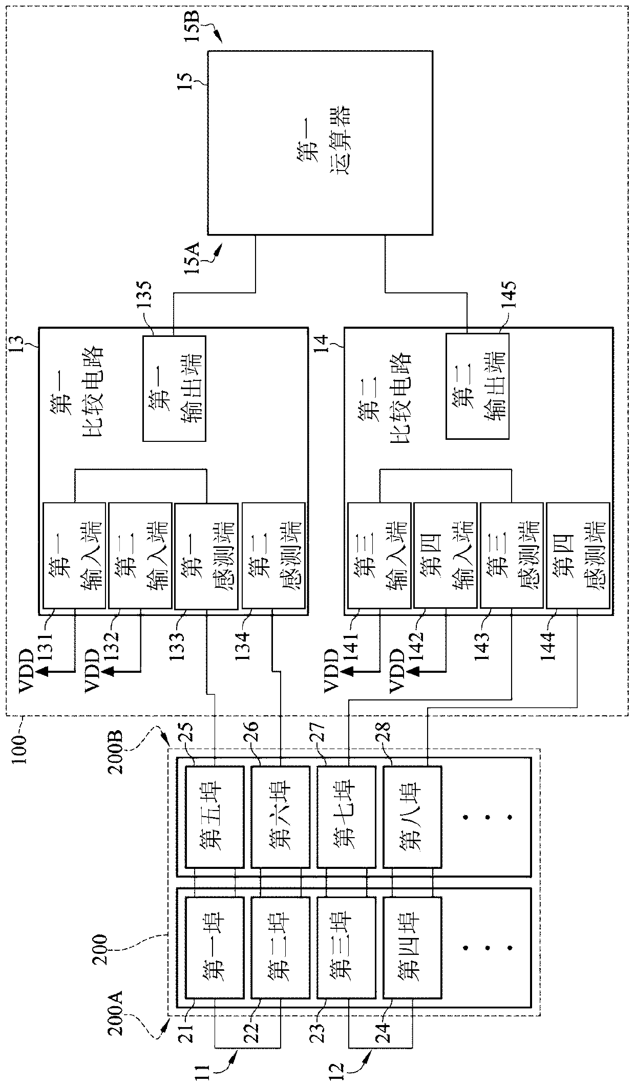
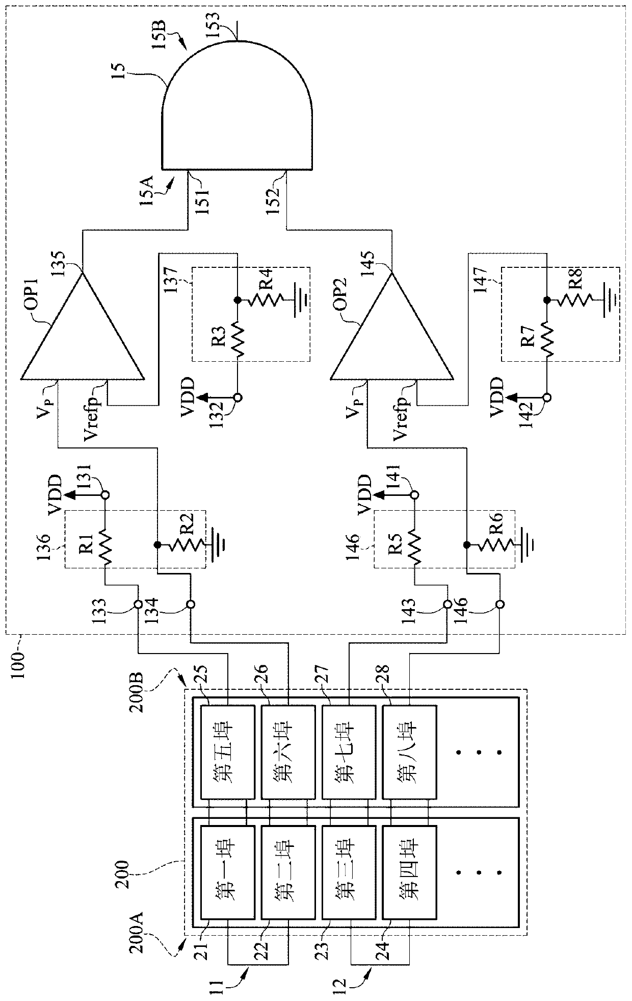
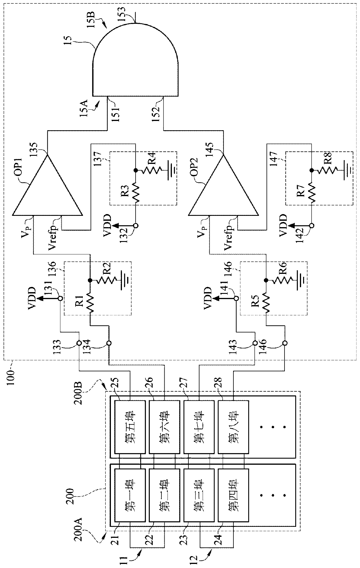
[0082] The detailed features and advantages of the present invention are described in detail below in the implementation manner, and its content is enough to make any person skilled in the art understand the technical content of the present invention and implement it accordingly, and according to the content disclosed in this specification, the scope of protection of the claims and With the accompanying drawings, any person skilled in the art can easily understand the related objects and advantages of the present invention. The following examples further illustrate the concept of the present invention in detail, but do not limit the scope of the present invention in any way.

[0083] The differential signal detecting device of the present invention is used for detecting a differential signal transmission line, and the differential signal transmission line may be, for example, a PCI-E cable, but not limited thereto. The following will take the PCI-E cable as an example to illus...


PUM


Abstract

The invention discloses a differential signal detection device which is used for detecting a differential signal transmission line, and two opposite sides of the differential signal transmission lineare respectively provided with a first port to a fourth port and a fifth port to an eighth port. The differential signal detection device comprises a first loop, a second loop, a first comparison circuit, a second comparison circuit and an arithmetic unit. The first loop is used for being electrically connected with the first port and the second port, and the second loop is used for being electrically connected with the third port and the fourth port. The first input end and the second input end of the first comparison circuit are used for being connected with a power end, the first sensing end of the first comparison circuit is electrically connected with the first input end and used for being connected with a fifth port, and the second sensing end is used for being connected with a sixthport. The third input end and the fourth input end of the second comparison circuit are used for being connected with a power end, the third sensing end is electrically connected with the third inputend and used for being connected with a seventh port, and the fourth sensing end is used for being connected with an eighth port. The input side of the arithmetic unit is electrically connected to the first output end and the second output end.

Description

technical field [0001] The invention relates to a detection device for a computer transmission line, in particular to a detection device for a PCI-E transmission line. Background technique [0002] A PCI-E cable is a current bus transmission line, which is used to connect between a computer host and peripheral devices to transmit data, or to connect different computer hosts to transmit data. PCI-E cables include PCIe signal ports, USB signal ports, PHY signal ports, SMBus signal ports, Prsnt signal ports, and P3V3 power signal ports. When it is not normal, it will make the function of the above-mentioned function signal port go wrong. [0003] At present, testing the PCIe signal and SMBus signal in the PCI-E cable is achieved through the Himalia hotplug (hotplug) / Each Card. However, there is currently no suitable test fixture for testing USB signals, PHY signals and P3V3 power signals. [0004] In view of this, in practice, there is indeed a need for an improved bus trans...

Claims


Application Information

Patent Timeline
IPC IPC(8): G06F11/22G01R31/02G01R31/08
CPCG06F11/221G01R31/08G01R31/50G01R31/58
Inventor 颜廷儒蔡惠民
Owner INVENTEC PUDONG TECH CORPOARTION
Learn More