Temperature control method and device
A temperature control method and target temperature technology, applied in the direction of temperature control, non-electric variable control, control/regulation system, etc., can solve the problems of waste of power resources, high cost, inability to automatically control the start and stop of fans, and reduce safety. The effect of hidden dangers and economic losses, saving installation costs and installation space
- Summary
- Abstract
- Description
- Claims
- Application Information
AI Technical Summary
Problems solved by technology
Method used
Image

Examples
Embodiment 1
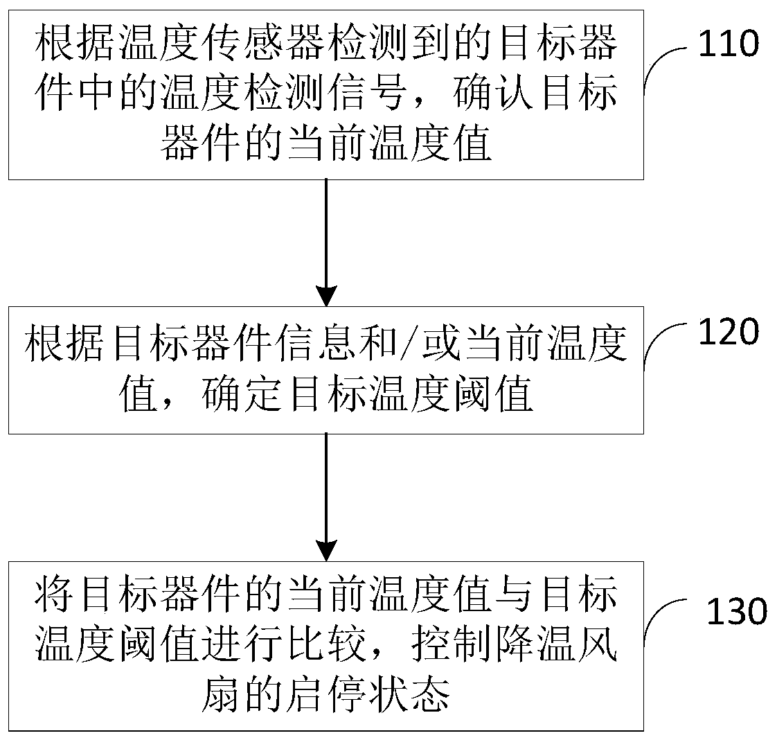
[0037] figure 1 It is a schematic flow chart of the temperature control method provided by Embodiment 1 of the present invention. This embodiment is applicable to the automatic cooling of electronic devices and electrical control devices to keep the components in a constant temperature state. This method can be executed by the temperature control device. Such as figure 1 As shown, the temperature control method specifically includes the following steps:
[0038] Step 110, confirming the current temperature value of the target device according to the temperature detection signal in the target device detected by the temperature sensor.
[0039] Specifically, the temperature sensor obtains the temperature detection signal in the target device and transmits it to the automatic controller, and the automatic controller performs temperature correction and filtering processing on the obtained temperature detection signal, removes the interference signal, and obtains an accurate curre...
Embodiment 2
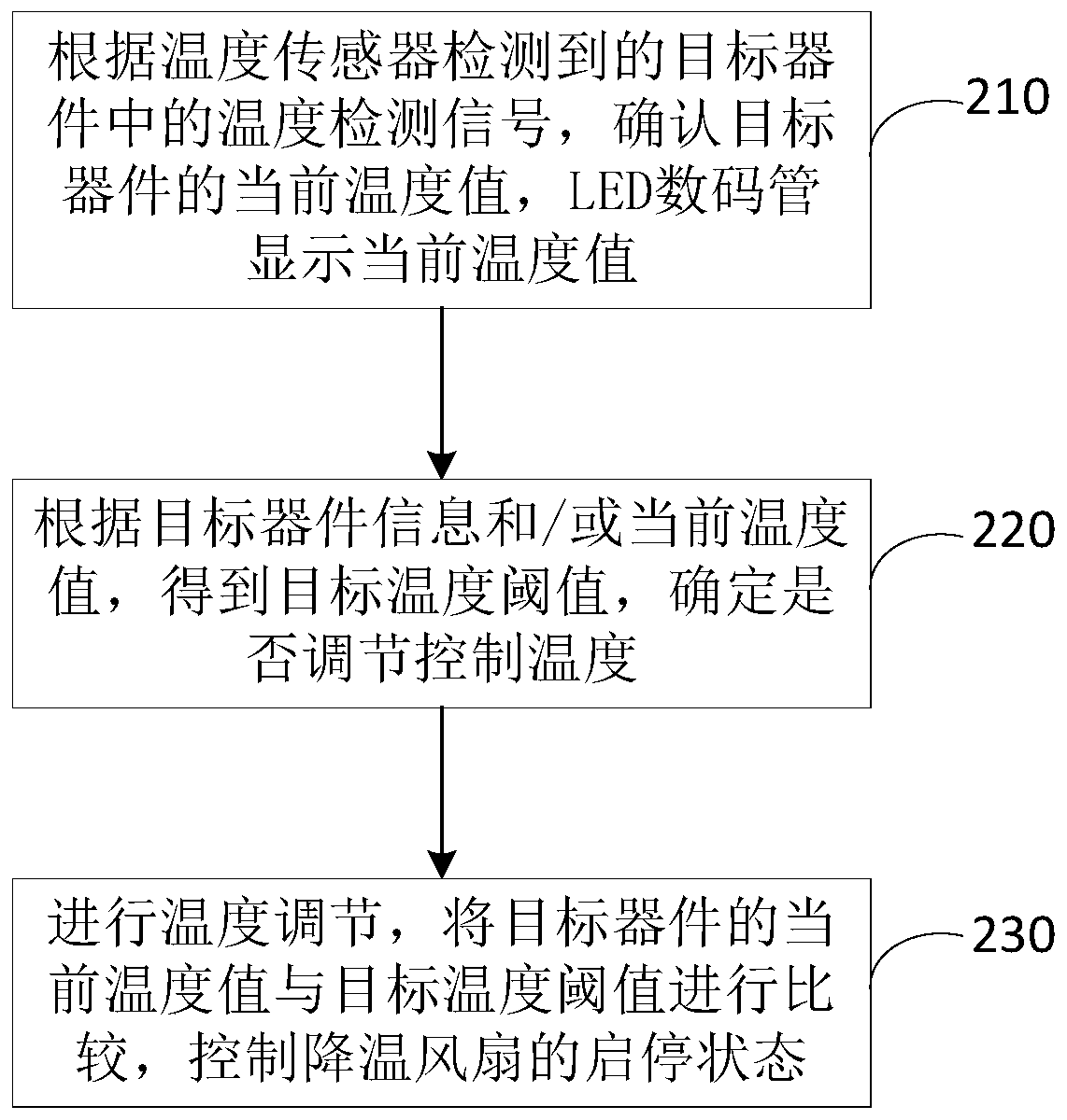
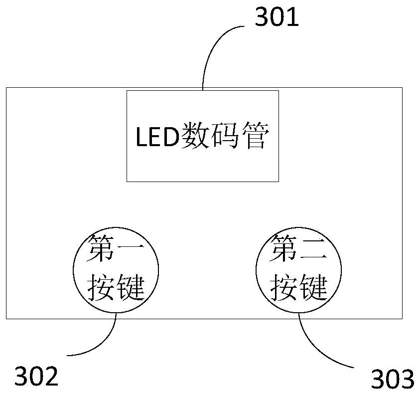
[0048] figure 2 It is a schematic flow chart of the temperature control method provided in Embodiment 2 of the present invention, image 3 The product structure diagram of the temperature control device provided by the embodiment of the present invention, this embodiment is based on the above embodiments, and the method can be executed by the temperature control device. Such as figure 2 As shown, it specifically includes the following steps:
[0049] Step 210, confirm the current temperature value of the target device according to the temperature detection signal in the target device detected by the temperature sensor, and the LED digital tube displays the current temperature value.
[0050] Step 220, obtain the target temperature threshold according to the target device information and / or the current temperature value, and determine whether to adjust the control temperature.
[0051]Wherein, to determine whether to adjust the control temperature, the target temperature t...
Embodiment 3
[0056] Figure 4 The structural block diagram of the temperature control device provided by Embodiment 3 of the present invention can execute the temperature control method provided by any embodiment of the present invention, and has corresponding functional modules and beneficial effects for executing the method. Such as Figure 4 As shown, the device includes:
[0057] The current temperature value confirmation module 401 is configured to confirm the current temperature value of the target device according to the temperature detection signal in the target device detected by the temperature sensor.
[0058] The target temperature threshold determination module 402 is configured to determine the target temperature threshold according to the target device information and / or the current temperature value.
[0059] Optionally, the target temperature threshold determination module 402 is specifically configured to: determine the target temperature threshold according to at least...
PUM
 Abstract
Description
Claims
Application Information
 - R&D
- Intellectual Property
- Life Sciences
- Materials
- Tech Scout
- Unparalleled Data Quality
- Higher Quality Content
- 60% Fewer Hallucinations
Browse by: Latest US Patents, China's latest patents, Technical Efficacy Thesaurus, Application Domain, Technology Topic, Popular Technical Reports.
© 2025 PatSnap. All rights reserved.Legal|Privacy policy|Modern Slavery Act Transparency Statement|Sitemap|About US| Contact US: help@patsnap.com