
Solid-liquid two-phase hydraulic design method used for deep-sea mining mine lifting pump

A technology for hydraulic design and deep-sea mining, which is applied to the components of pumping devices for elastic fluids, mining minerals, and special mining, etc., and can solve the problems of easy blockage, poor wear resistance, and low solid-liquid conveying efficiency.

Active Publication Date: 2019-09-10
ZHEJIANG SCI-TECH UNIV
View PDF5 Cites 6 Cited by
  • Summary
  • Abstract
  • Description
  • Claims
  • Application Information

AI Technical Summary

Problems solved by technology

[0005] The invention mainly solves the problems of low solid-liquid transport efficiency, easy blockage, poor wear resistance and short service life in the prior art, and provides a solid-liquid two-phase hydraulic design method for deep-sea mining lifting pumps, which has the advantages of Advantages of compact structure, smooth flow, strong wear resistance, high solid-liquid conveying efficiency and long service life

Method used


Image

  • Solid-liquid two-phase hydraulic design method used for deep-sea mining mine lifting pump
  • Solid-liquid two-phase hydraulic design method used for deep-sea mining mine lifting pump
  • Solid-liquid two-phase hydraulic design method used for deep-sea mining mine lifting pump

Examples


Embodiment

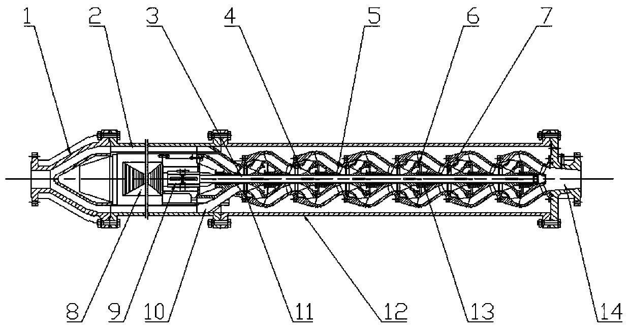
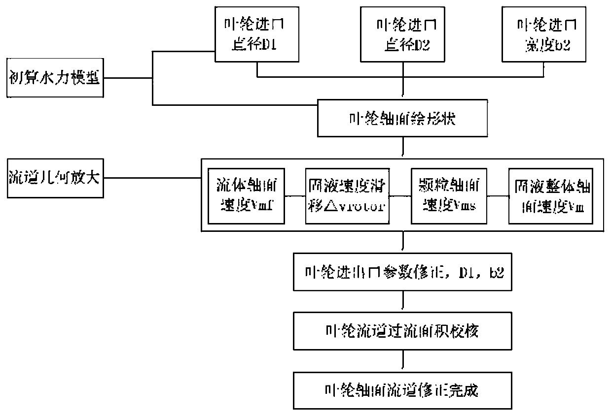
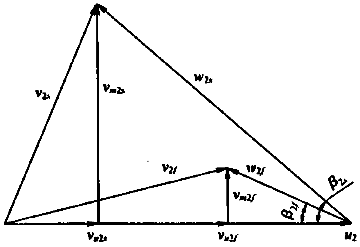
[0053] Example: such as Figure 1-10 As shown, a solid-liquid two-phase hydraulic design method for deep-sea mining pumps, the solid-liquid slurry drives the multi-stage long-axis rotor 3 through the wet submersible motor 8 to drive the six rotating impellers on the multi-stage long-axis rotor 3 The stationary guide vane body 5 in 4 enters the annular flow channel 2 inside the outer cylinder 12 from the inlet section 1, and drives the main shaft 3 to drive the sand discharge tray 7 in the rotating impeller 4 to avoid mortar silting during solid-liquid slurry transportation The channel affects the drainage efficiency. Then pass through the suction section 10 under the pressure of the rotation of the guide vane 5, and finally discharge from the discharge section 14, through the connection between the suction section 10 and the rotating impeller 4, the impeller sealing ring 11, the rotating impeller 4 and the stationary guide vane body 5 The front end is provided with a pump bod...


PUM


Abstract

The invention relates to a solid-liquid two-phase hydraulic design method used for a deep-sea mining mine lifting pump and belongs to the technical field of deep-sea mining mine lifting pumps. Solid-liquid slurry enters a ring-shaped runner in an outer cylinder from an inlet section in the manner that a driving motor drives a driving main shaft to drive guide vanes in multiple impellers, and thenthe solid-liquid slurry passes through a suction section, and the solid-liquid slurry is discharged from a split section finally under rotating pressurizing of the guide vanes, wherein the impellers and the guide vanes are ring-shaped rotation body structures. By means of the mine lifting pump, clean water runner design calculation is combined, the slurry conveying theory is also met, and design of the runner shape is achieved from the aspects of liquid flow speed and overflowing section area dependency, slurry viscosity precipitation and global viscosity changing. The beneficial effects thatthe structure is compact, flow passing is smooth, wear resistance is high, the solid-liquid conveying efficiency is high, and the service life is long are achieved. The enough runner axial passing capability is ensured, and particles are prevented from blocking a runner. The overflowing speed is increased, axial vortexes are eliminated, it is ensured that downstream through flow has enough kineticenergy, and local vortexes and blockage are effectively prevented.

Description

technical field [0001] The invention relates to the technical field of deep-sea mining lifting pumps, in particular to a solid-liquid two-phase hydraulic design method for deep-sea mining lifting pumps. Background technique [0002] At present, with the rapid development of human civilization and industrialization, land mineral resources are becoming increasingly depleted, and the importance of marine mining has gradually become prominent. As a system engineering, deep-sea mining has the cutting-edge and advanced technology as a whole. Among them, the lifting ore pump for slurry transportation provides power for the entire delivery pipeline, and the solid-liquid slurry is pressurized through the multi-stage circuitous impeller and guide vane flow channel. The existing lifting pump does not perform well in particle passage and efficiency. good. In 1988, Japan's Ebara Company developed two 8-stage submersible pumps, with a flow rate of 450m3 / h, a head of 760m, a power of 1200...

Claims


Application Information

Patent Timeline
Patent Type & Authority Applications(China)
IPC IPC(8): F04D7/00F04D13/08F04D29/18F04D29/40E21C50/00
CPCE21C50/00F04D7/00F04D13/086F04D29/185F04D29/406
Inventor 宿向辉唐臻吉李昳朱祖超王艳萍金星
Owner ZHEJIANG SCI-TECH UNIV
Learn More