Corrugated sensor, corrugation reconstruction method and application thereof

A sensor and corrugated technology, applied in the field of corrugated sensors, can solve the problems of large reconstruction error, large spot recognition and positioning error, and consumption, so as to avoid dislocation spot phenomenon, improve imaging correction effect, and increase application depth.

Active Publication Date: 2019-09-13
SHENZHEN INST OF ADVANCED TECH
View PDF4 Cites 3 Cited by
  • Summary
  • Abstract
  • Description
  • Claims
  • Application Information

AI Technical Summary

Problems solved by technology

However, limited by the structural design of the existing ripple sensor, the correction of the current ripple sensor for underwater imaging is still not ideal, for example, (1) Figure 9 and 10 , the prior art moire sensor uses a transmissive frosted glass scattering plate as the light spot to attach the imaging device, the upper and lower surfaces of the scatterer will form misaligned light spots, the recognition and positioning e...

Method used


Image

  • Corrugated sensor, corrugation reconstruction method and application thereof
  • Corrugated sensor, corrugation reconstruction method and application thereof
  • Corrugated sensor, corrugation reconstruction method and application thereof

Examples


Embodiment Construction

[0050] The application will be described in detail below in conjunction with specific implementations shown in the accompanying drawings. However, these implementations do not limit the present application, and any structural, method, or functional changes made by those skilled in the art based on these implementations are included in the protection scope of the present application.

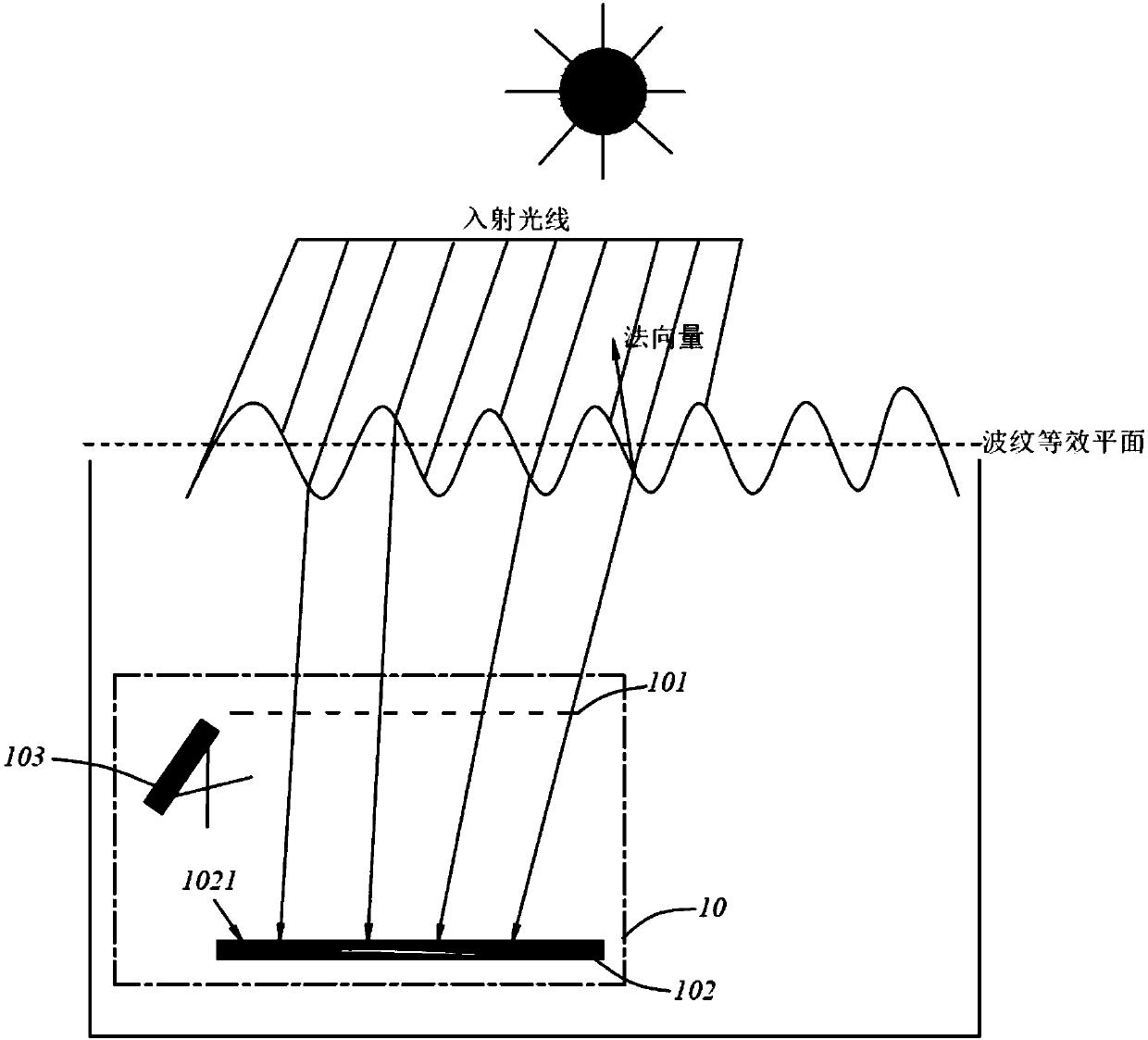
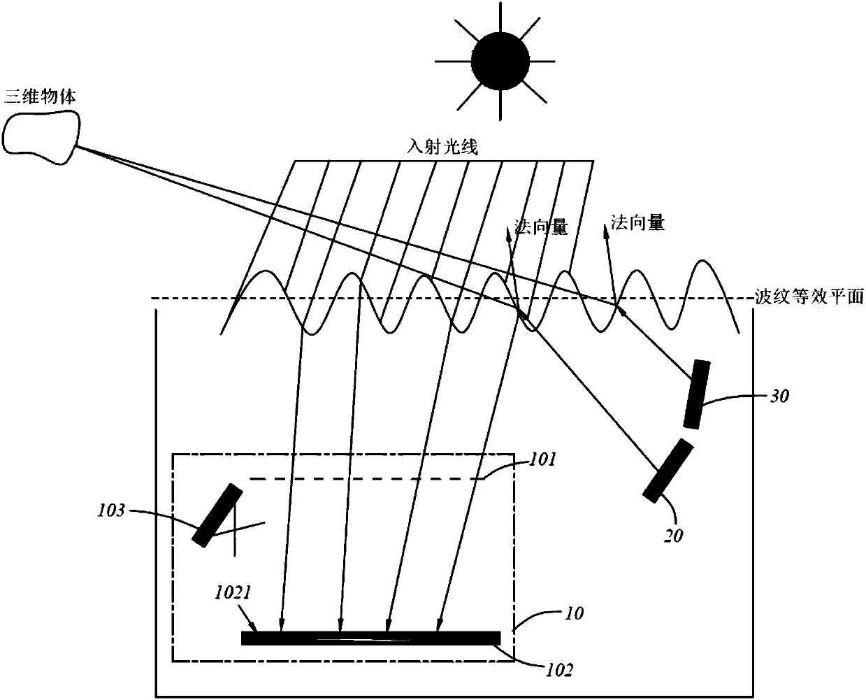
[0051] ginseng figure 1 , to introduce an embodiment of the moire sensor 10 of the present invention. In this embodiment, the moire sensor 10 includes a sampling array 101 , a reflector 102 , a first imaging element 103 and a control element (not shown).

[0052]The sampling array 101 is used for sampling the refracted rays passing through the corrugations. It should be noted that, in the embodiment of the present invention, the ripple sensor 10 is usually arranged under the water surface, and then samples the refracted light incident into the water through the ripples in the air, but in some o...


PUM


Abstract

The present invention discloses a corrugated sensor, a corrugation reconstruction method and application thereof. The corrugated sensor comprises: a sampling array, for sampling the refracted light passing through the corrugation; a reflecting plate, wherein the reflecting plate comprises a light receiving surface, and the light receiving surface is configured to receive the sampled refracted light to form sampling spots; a first imaging element, for imaging the light receiving surface to obtain distribution information of the sampling spots; and a control element, for reconstructing the corrugation distribution according to the distribution information of the sampling spots, relative position information of the reflecting plate and the first imaging element, position information of the array unit in the sampling array corresponding to the sampling spot, and direction information of the incident light corresponding to the sampled refracted light. According to the technical scheme of the present invention, a reflecting plate is used as the spot imaging element for sampling the refracted light, so that the misalignment flare phenomenon of transmissive imaging is avoided, the depth applicable to the underwater is increased, and the imaging correction effect in the water surface-to-sky imaging application is improved.

Description

technical field [0001] The invention belongs to the technical field of underwater air-to-air imaging, and in particular relates to a ripple sensor, a ripple reconstruction method and an application thereof. Background technique [0002] For the observation of targets on the water surface, real-time observation can be achieved by establishing monitoring devices on land on the water surface, or applying periscopes underwater based on the principle of light reflection. However, the concealment of these observation methods is poor, and it is easy to expose the location information of the monitor, thus limiting the application in fields such as border and coastal defense. [0003] Correspondingly, there are some huge challenges in the direct observation of targets above the water surface from underwater, see Figure 7 As shown, the ripples on the surface of the water body will cause random scattering interference to the incident light. When the ripples are small and the water sur...

Claims


Application Information

Patent Timeline
IPC IPC(8): G01C11/34
CPCG01C11/34
Inventor 罗松鲁远甫焦国华董玉明周志盛
Owner SHENZHEN INST OF ADVANCED TECH
Why Eureka
Try Eureka