Novel laser rangefinder

A rangefinder and laser technology, which is applied in the field of laser rangefinders, can solve problems such as numerous parts, complex structure of rangefinders, and loss of light energy, so as to optimize component design, avoid light energy loss, and reduce optical component settings. effect of number

Pending Publication Date: 2019-05-28
重庆市华阳光学仪器有限公司
View PDF0 Cites 0 Cited by
  • Summary
  • Abstract
  • Description
  • Claims
  • Application Information

AI Technical Summary

Problems solved by technology

The existing range finder includes a telescopic system, a laser emitting system, a laser receiving system and a display system, but because there are multiple optical paths in the range finder, if the overall layout of the range finder is unreasonable, it is easy to cause the range finder to fail. The structure is complex and there are many parts. Usually, part of the optical path of the laser emitting or receiving system is shared with the optical path of the telephoto system to form a compact mechanism. The liquid crystal display is built into the focal plane of the telephoto system, but this will cause a large loss of light energy.

Method used


Image

  • Novel laser rangefinder

Examples


Embodiment Construction

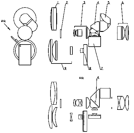
[0015] The present invention will now be described in further detail in conjunction with the accompanying drawings, which are simplified schematic diagrams illustrating the basic structure of the present invention in a schematic manner.

[0016] The present invention provides a novel rangefinder, including a telescopic system, a laser system, and a display system, wherein the telescopic objective lens 1 and the rectangular prism 5 are on the same horizontal axis, and a liquid crystal screen 2, a projection Mirror group 3, dichroic prism 4, the liquid crystal screen 2 and the projection mirror group 3 are on the same horizontal axis, the dichroic prism 4 has a C surface, the laser element 8 and the lens group 9 form a single laser component, which It is characterized in that: the telescopic system includes a telescopic objective lens 1, a dichroic prism 4, a rectangular prism 5 and a telescopic system eyepiece group 6; the laser system includes a telescopic objective lens 1, a d...


PUM


Abstract

The invention relates to the technical field of laser rangefinders, in particular to a novel laser rangefinder. The novel laser rangefinder comprises a telescoping system, a laser transmission or receiving system and a display system. A light path of the telescoping system and a light path of the laser transmission or receiving system partially coincide, a light path of the display system and thelight path of the telescoping system partially coincide, in this way, the arrangement number of rangefinder optical parts can be reduced, a display liquid crystal screen is arranged outside the lightpath of the telescoping system, and accordingly the situation is avoided that since the display liquid crystal screen is arranged in the light path, light energy loss is caused.

Description

technical field [0001] The invention relates to a measuring tool, in particular to a laser range finder. Background technique [0002] The laser range finder is an instrument that uses laser to accurately measure the distance of the target. The existing range finder includes a telescopic system, a laser emitting system, a laser receiving system and a display system, but because there are multiple optical paths in the range finder, if the overall layout of the range finder is unreasonable, it is easy to cause the range finder to fail. The structure is complicated, and there are many parts. Usually, part of the optical path of the laser emitting or receiving system is shared with the optical path of the telephoto system to form a compact mechanism. The liquid crystal display is built into the focal plane of the telephoto system, but this will cause a large loss of light energy. Contents of the invention [0003] In view of the technical problems in the background technology...

Claims


Application Information

Patent Timeline
IPC IPC(8): G01S17/08G01S7/481
Inventor 蒲春华伏容
Owner 重庆市华阳光学仪器有限公司
Why Eureka
Try Eureka