
Backlight module and display device

a backlight module and display device technology, applied in the field of display technologies, can solve the problems of light energy loss, reducing serious energy loss of wide-angle light, etc., and achieve the effect of preventing a light energy loss and improving a light output ratio

Active Publication Date: 2022-04-26
HUIZHOU CHINA STAR OPTOELECTRONICS TECHNOLOGY CO LTD
View PDF8 Cites 0 Cited by
  • Summary
  • Abstract
  • Description
  • Claims
  • Application Information

AI Technical Summary

Benefits of technology

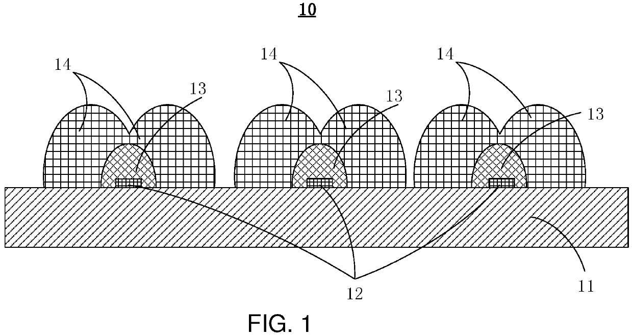
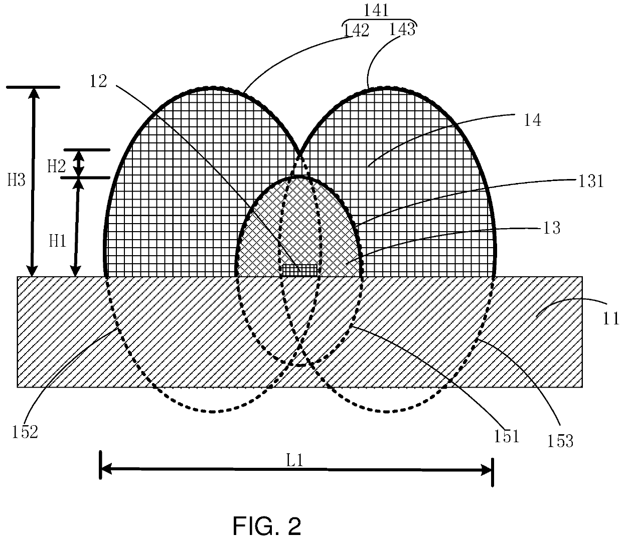
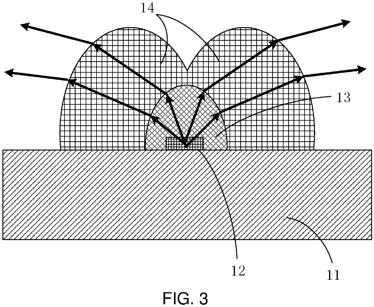
The present invention provides a backlight module. The module has a circuit board with multiple light emitting elements on its side surface. The light output surface of at least one of these elements is covered with a curved surface layer. This design prevents total reflection of light at the output surface and improves the light output ratio, reducing energy loss.

Problems solved by technology

However, in a lamp board structure of the mini-LED, wide-angle light is easily returned to the circuit board due to a total internal reflection in the adhesive layer at the air interface.
A reflectivity of a white lacquer of the circuit board is only 85%, which is far less than a reflection sheet (reflectivity of 95% or more), so an energy loss of the wide-angle light is serious.
That is, in the prior art, light easily encounters a total reflection at a light output surface of an encapsulation layer, causing a light energy loss and reducing a light output ratio.

Method used


Image

  • Backlight module and display device
  • Backlight module and display device
  • Backlight module and display device

Examples


Embodiment Construction

[0035]The technical solutions in the embodiments of the present invention are clearly and completely described in the following with reference to the accompanying drawings in the embodiments of the present invention. Obviously, the described embodiments are only a part of the embodiments of the present invention, and not all of the embodiments. Based on the embodiments in the present invention, all other embodiments obtained by those skilled in the art without creative efforts are within the scope of the present invention.

[0036]In the description of the present invention, it is to be understood that the term “center”, “longitudinal”, “lateral”, “length”, “width”, “thickness”, “upper”, “lower”, “front”, “rear”, “left”, “right”, “vertical”, “horizontal”, “top”, “bottom”, “inner”, “outer”, “clockwise”, “counterclockwise”, “axial”, “radial”, “circumferential orientation or positional relationship”, or the like indicating a positional relationship of the orientation shown in the accompan...


PUM

PropertyMeasurementUnit
refractive indexaaaaaaaaaa
reflectivityaaaaaaaaaa

Abstract

An embodiment of the present invention discloses a backlight module and a display device. The backlight module includes a circuit board. A side surface of the circuit board is provided with a plurality of light emitting elements spaced apart from each other. A light output surface of at least one of the light emitting elements is covered with a first encapsulation layer. A side surface of the first encapsulation layer away from the at least one light emitting elements is a curved surface.

Description

FIELD OF INVENTION[0001]The present invention relates to the field of display technologies, and in particular, to a backlight module and a display device.BACKGROUND OF INVENTION[0002]At the present stage, the development of display technologies is changing with each passing day, and an emergence of various screen technologies provides unlimited possibilities for electronic terminals, especially rapid applications of display technologies represented by organic light emitting diodes (OLEDs).[0003]At present, since mini light emitting diodes (mini-LEDs) can achieve ultra-thin and multi-partition, and are products using small-size chips, the mini-LEDs can be compared with OLED products in realistic effect. Furthermore, in terms of material cost, the mini-LEDs can be more competitive than OLEDs and are favored by backlight display industries.[0004]When the mini-LEDs on the market are used as a backlight, the flip chip is usually die-bonded on the circuit board. At this time, the mini-LED...

Claims


Application Information

Patent Timeline
Patent Type & Authority Patents(United States)
IPC IPC(8): H01L33/58H01L33/54F21V8/00
CPCH01L33/58G02B6/0068G02B6/0073H01L33/54G02F1/133603G02F1/133606G02F1/133614H01L25/0753G02B6/0013
Inventor LIN, YUEXIAQIU, YONGYUAN
Owner HUIZHOU CHINA STAR OPTOELECTRONICS TECHNOLOGY CO LTD
Learn More