
Display panel and display device

A display panel and display area technology, applied in static indicators, optics, instruments, etc., can solve the problem of incompatibility between light transmission and display in the camera area under the screen

Inactive Publication Date: 2019-09-13
WUHAN CHINA STAR OPTOELECTRONICS SEMICON DISPLAY TECH CO LTD
View PDF8 Cites 51 Cited by
  • Summary
  • Abstract
  • Description
  • Claims
  • Application Information

AI Technical Summary

Problems solved by technology

[0004] The present invention provides a display panel to solve the technical problem that the existing display panel cannot have both light transmission and display in the camera area under the screen

Method used


Image

  • Display panel and display device
  • Display panel and display device
  • Display panel and display device

Examples


Embodiment Construction

[0030] The following will clearly and completely describe the technical solutions in the embodiments and / or examples of the present invention in combination with the specific embodiments of the present invention. Obviously, the embodiments and / or examples described below are only part of the implementation of the present invention. Schemes and / or examples, but not all embodiments and / or examples. Based on the embodiments and / or examples of the present invention, all other embodiments and / or examples obtained by those of ordinary skill in the art without creative work shall fall within the protection scope of the present invention.

[0031] The directional terms mentioned in the present invention, such as [Up], [Down], [Left], [Right], [Front], [Back], [Inner], [Outer], [Side], etc., are for reference only The direction of the additional schema. Therefore, the directional terms used are used to illustrate and understand the present invention, rather than to limit the present inve...


PUM


Abstract

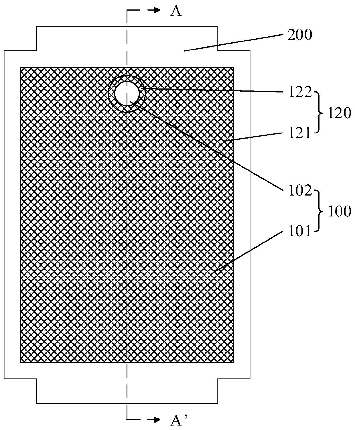
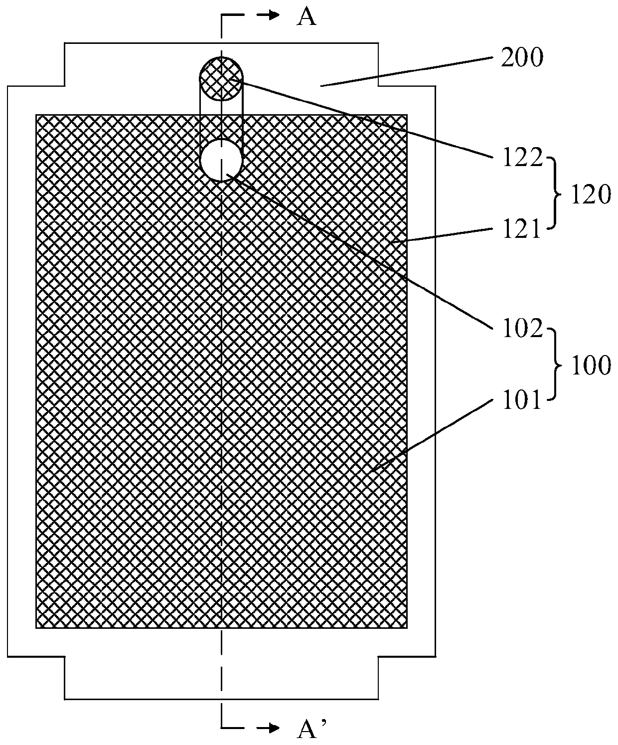
The invention provides a display panel and a display device. The display panel comprises a first display area and a second display area. The second display area corresponds to the position of the electronic component. The display panel includes: a driving circuit layer and a light-emitting function layer. The driving circuit layer is provided with a through hole in the second display area. The driving circuit layer comprises a first pixel driving circuit area and a second pixel driving circuit area. A first pixel driving circuit used for driving pixels in the first display area to work is formed in the first pixel driving circuit area, and a second pixel driving circuit used for driving pixels in the second display area to work is formed in the second pixel driving circuit area. Accordingto the display panel, the through hole is formed in the area, corresponding to the under-screen electronic element, of the driving circuit layer, the pixel driving circuit corresponding to the pixel corresponding to the under-screen electronic element area is arranged in other display areas or non-display areas, and the technical problem that an under-screen camera area of an existing display panel is pervious to light and cannot achieve display at the same time is solved.

Description

Technical field [0001] The present invention relates to the field of display, in particular to a display panel and a display device. Background technique [0002] With the development of full-screen technology, the technology of placing electronic components such as cameras under the display is a development trend. However, in the prior art, in order to ensure the lighting effect of the electronic components under the screen, such as the camera, the materials above the camera (including the TFT circuit, the light-emitting layer, the cathode structure, etc.) need to be removed, that is, the hole-digging technology affects the display effect. [0003] Therefore, the existing display panel has a technical problem that the light transmission and display of the camera area under the screen cannot be combined, and it needs to be improved. Summary of the invention [0004] The present invention provides a display panel to solve the technical problem that the existing display panel cannot ...

Claims


Application Information

Patent Timeline
Patent Type & Authority Applications(China)
IPC IPC(8): G09G3/3225G09G3/36G02F1/133G02F1/1333H01L27/32
CPCG09G3/3225G09G3/36G02F1/133G02F1/1333H10K59/12G09G3/3611
Inventor 王威黄情
Owner WUHAN CHINA STAR OPTOELECTRONICS SEMICON DISPLAY TECH CO LTD
Learn More