
Ventilator for cardiology

A ventilator and cardiology technology, applied in the field of ventilators, can solve the problem that there is no way to automatically switch the intake and exhaust

Inactive Publication Date: 2019-09-17
周保利
View PDF1 Cites 0 Cited by
  • Summary
  • Abstract
  • Description
  • Claims
  • Application Information

AI Technical Summary

Problems solved by technology

The external power supply of the portable ventilator of the utility model can supply power for the ventilator host when there is a power failure or a power shortage, and at the same time serve as the base of the ventilator host to fix the ventilator host, and can be fixed on the platform of the trolley together with the ventilator host as a whole. Ensure that the patient can also use the ventilator host normally during the transfer process, but the disadvantage of this invention is that there is no way to automatically switch between the intake and exhaust states

Method used


Image

  • Ventilator for cardiology
  • Ventilator for cardiology
  • Ventilator for cardiology

Examples


specific Embodiment approach 1

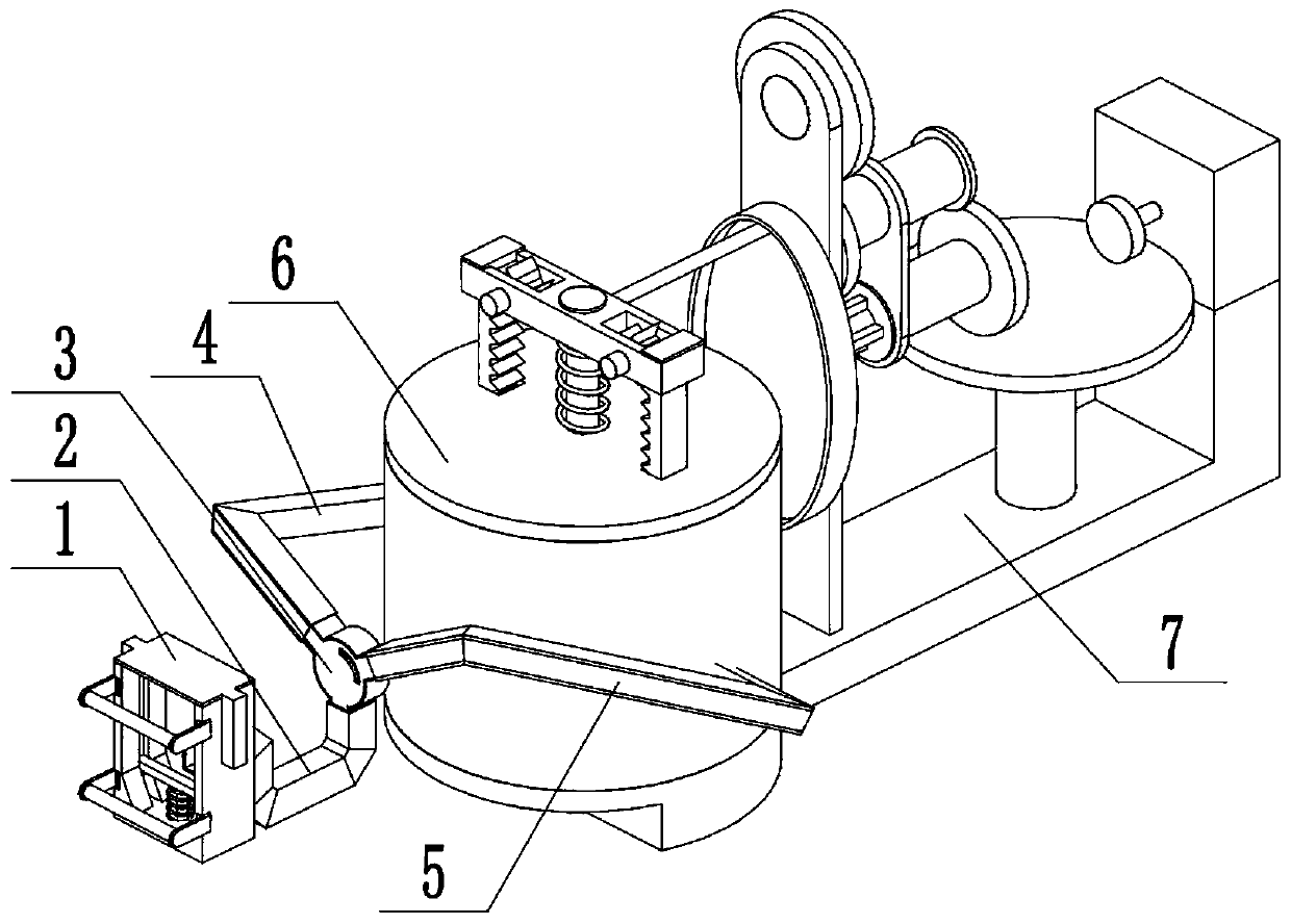
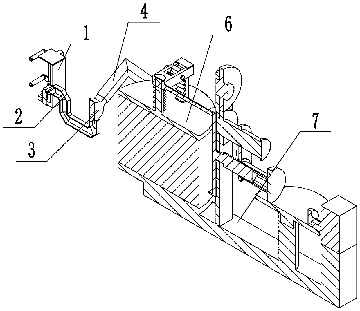
[0042] Combine below Figure 1-25 Describe this embodiment, a ventilator for cardiology, including a mask fixing assembly 1, a connecting tube 1 2, a gas exchange assembly 3, a connecting tube 2 4, a connecting tube 3 5, a gas drive cylinder 6 and an input assembly 7 , the face mask fixed assembly 1 is fixedly connected and communicated with the connecting pipe one 2, the connecting pipe one 2 is fixedly connected and communicated with the gas exchange assembly 3, the connecting pipe two 4 and the connecting pipe three 5 are connected with the gas exchange assembly 3 and connected, the connecting pipe 2 4 and the connecting pipe 3 5 are respectively connected and communicated with the gas driving cylinder 6 , and the gas driving cylinder 6 is connected with the input assembly 7 .

specific Embodiment approach 2

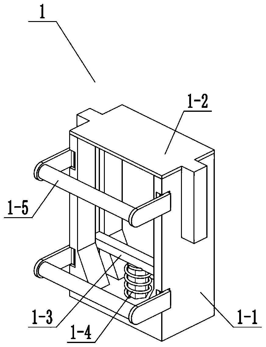
[0044] Combine below Figure 1-25 Illustrate this embodiment, this embodiment will further explain Embodiment 1, the mask fixing assembly 1 includes a mask fixing outer frame 1-1, a mask upper frame 1-2, a mask lower frame 1-3, and a lower frame push spring 1-4, rubber connection belt 1-5, inner push spring 1-6, inner sliding rod 1-7, side wall hollow groove 1-8, side wall hinged column 1-9, middle end chute 1-10 , ear plate 1-11, prismatic sliding hole 1-12, rubber belt 1-13, inner push spring 2 1-14, inner push spring 3 1-15, side wall rectangular rod 1-16, side wall rectangular rod Two 1-17 and inner hollow groove 1-18, the upper frame 1-2 of the mask is connected with the fixed outer frame 1-1 of the mask, and the lower end of the lower frame 1-3 of the mask is slidably connected to the inner wall of the fixed outer frame 1-1 of the mask The lower end of the lower frame push spring one 1-4 is arranged between the lower frame 1-3 of the mask and the lower side of the inner...

specific Embodiment approach 3

[0047] Combine below Figure 1-25 Describe this embodiment, this embodiment will further explain Embodiment 1, the gas exchange assembly 3 includes a sealing end cover 3-1, a gas exchange assembly 3-2, a gas exchange outer frame 3-3, and an inner arc-shaped slide bar 3-4, slide bar push spring four 3-5, connected air hole one 3-6, drive plate 3-7, connected seven holes two 3-8, connected groove one 3-9, connected groove two 3-10 and connected groove Three 3-11, the gas exchange combination 3-2 is connected with the gas exchange outer frame 3-3, the sealing end cover 3-1 is fixedly connected to the front end of the gas exchange outer frame 3-3, the gas exchange combination 3-2 is connected with the gas exchange outer frame 3-3 The rear end face of the sealing end cover 3-1 is fitted, the inner arc-shaped sliding rod 3-4 is fixedly connected to the sealing end cover 3-1, and the sliding rod push spring four 3-5 is socketed and connected to the inner arc-shaped sliding rod 3- 4,...


PUM


Abstract

The invention relates to a ventilator, more specifically to a ventilator for cardiology. The ventilator can fix patient skulls of different specifications through a mask fixing assembly; a gas exchange assembly can conveniently control a passive inhalation and exhalation process of the patient; the gas exchange assembly is connected to the mask fixing assembly; a gas driving cylinder can conveniently inject air into the patient's lungs and suck in air; and an inhalation and exhalation volume can be conveniently adjusted by the gas driving cylinder. The ventilator includes the mask fixing assembly, a connecting tube 1, the gas exchange assembly, a connecting tube 2, a connecting tube 3, the gas drive cylinder and an input assembly; due to different sizes of the patients' skulls, an upper frame of a mask slides relatively to ear plates through inner push springs, and can be fitted to the upper side of the patient's head, and a lower frame of the mask relatively slides in a prismatic sliding hole, so that the patient's skull lower jaw fits with the lower frame of the mask; and a rubber belt and a rubber connecting belt relatively slid, thereby achieving fixation of patients' heads in different specifications.

Description

technical field [0001] The invention relates to a ventilator, more specifically a ventilator for cardiology. Background technique [0002] For example, the patent number is CN201520479938.6 portable ventilator external power supply and ventilator. The portable ventilator external power supply includes a base and a rechargeable battery installed in the base. It is used for accommodating the bottom of a ventilator main unit, and the top surface of the base is formed with a plurality of positioning columns in the storage groove for placing and positioning the ventilator main unit, and the base is provided with the charging unit. The charging interface to which the battery is electrically connected and the power supply interface for supplying power to the ventilator host. The external power supply of the portable ventilator of the utility model can supply power for the ventilator host when there is a power failure or a power shortage, and at the same time serve as the base of t...

Claims


Application Information

Patent Timeline
IPC IPC(8): A61M16/00A61M16/06
CPCA61M16/00A61M16/0003A61M16/0605A61M2205/33
Inventor 周保利
Owner 周保利
Learn More