
Air chamber of circulating fluidized bed boiler and circulating fluidized bed boiler

A technology of circulating fluidized bed and air chamber, which is applied in the field of boilers and can solve problems such as uncontrollable intake air volume

Pending Publication Date: 2021-08-10
国能神福(龙岩)发电有限公司 +1
View PDF0 Cites 0 Cited by
  • Summary
  • Abstract
  • Description
  • Claims
  • Application Information

AI Technical Summary

Problems solved by technology

[0004] The purpose of the embodiment of the present application is to provide an air chamber of a circulating fluidized bed boiler and a circulating fluidized bed boiler, which can solve the problem that the intake air volume cannot be controlled

Method used


Image

  • Air chamber of circulating fluidized bed boiler and circulating fluidized bed boiler
  • Air chamber of circulating fluidized bed boiler and circulating fluidized bed boiler
  • Air chamber of circulating fluidized bed boiler and circulating fluidized bed boiler

Examples


Embodiment Construction

[0024] The technical solutions in the embodiments of the present application will be clearly and completely described below in conjunction with the drawings in the embodiments of the present application. Apparently, the described embodiments are part of the embodiments of the present application, not all of them. Based on the embodiments in this application, all other embodiments obtained by persons of ordinary skill in the art without creative efforts fall within the protection scope of this application.

[0025] The terms "first", "second" and the like in the specification and claims of the present application are used to distinguish similar objects, and are not used to describe a specific sequence or sequence. It is to be understood that the data so used are interchangeable under appropriate circumstances such that the embodiments of the application can be practiced in sequences other than those illustrated or described herein. In addition, "and / or" in the specification and...


PUM


Abstract

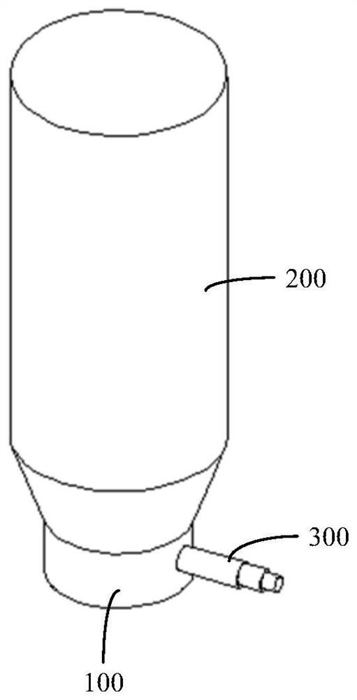
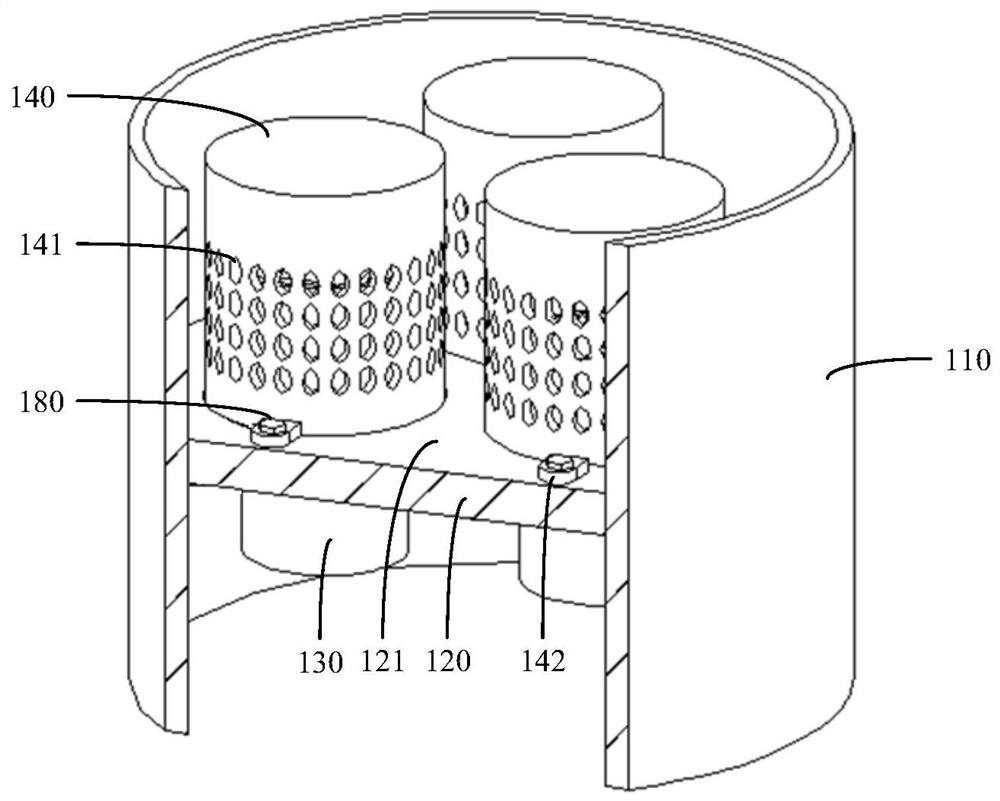
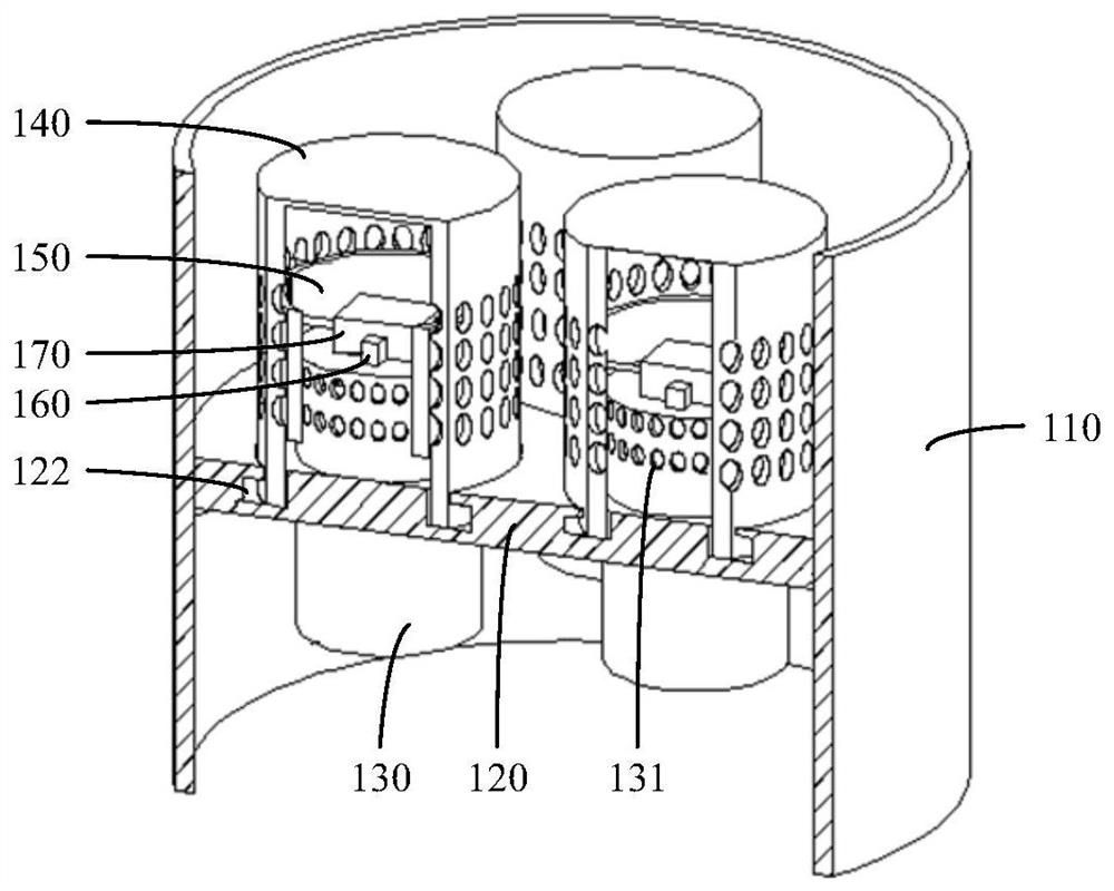
The invention discloses an air chamber of a circulating fluidized bed boiler and the circulating fluidized bed boiler. The air chamber comprises a shell which is provided with an air inlet side and an air outlet side, an air distribution plate, an air guide pipe, an air cap, a movable baffle and a driving mechanism; the air distribution plate is arranged in the shell, the air distribution plate is provided with a first surface and a second surface which are opposite to each other, the first surface faces the air inlet side, and the second surface faces the air outlet side; the air guide pipe is arranged on the air distribution plate, the first end of the air guide pipe is located on the air inlet side, the second end of the air guide pipe is located on the air outlet side, and a first air outlet is formed in the second end; the air cap is arranged on the air distribution plate, the air cap is located on the air outlet side, the air cap is arranged outside the second end of the air guide pipe in a sleeving mode, and the air cap is provided with a second air outlet; the movable baffle is arranged between the second end of the air guide pipe and the air cap; and the driving mechanism is arranged in the shell, the driving mechanism is connected with the movable baffle, and the driving mechanism drives the movable baffle to move so as to adjust the air inlet amount of the air chamber. According to the scheme, the problem that the air inflow cannot be controlled can be solved.

Description

technical field [0001] The application belongs to the technical field of boilers, and in particular relates to an air chamber of a circulating fluidized bed boiler and a circulating fluidized bed boiler. Background technique [0002] The circulating fluidized bed boiler adopts the clean coal combustion technology with the highest degree of industrialization. The circulating fluidized bed boiler adopts fluidized combustion. The biggest difference between it and the bubbling fluidized bed combustion technology is that the operating wind speed is high, which strengthens combustion and desulfurization and other heterogeneous reaction processes, the boiler capacity can be expanded to a large capacity acceptable to the electric power industry. The circulating fluidized bed boiler has solved the basic problems of heat, mechanics, material science and engineering problems such as expansion, wear and overheating. , has become an advanced technology for the utilization of flame retard...

Claims


Application Information

Patent Timeline
Patent Type & Authority Applications(China)
IPC IPC(8): F23C10/20
CPCF23C10/20F23C2206/10
Inventor 姜国锋李小珍李金进
Owner 国能神福(龙岩)发电有限公司
Learn More