Landing buffering device for unmanned aerial vehicle

The technology of a buffer device and unmanned aerial vehicle, which is applied in the field of unmanned aerial vehicles, can solve the problems of easily broken landing gear body, no shock absorption device, easy landing and unstable landing, etc., and achieves good buffer protection effect, good buffer effect and reliability. high sex effect

Inactive Publication Date: 2019-09-20
智飞智能装备科技东台有限公司
View PDF10 Cites 4 Cited by
  • Summary
  • Abstract
  • Description
  • Claims
  • Application Information

AI Technical Summary

Problems solved by technology

[0002] At present, UAVs have been widely used in aerial remote sensing, meteorological research and agricultural aerial broadcasting, especially in war, they have special advantages and can be widely used in aerial reconnaissance, surveillance, communication, anti-submarine and electronic jamming, etc. However, in When using a UAV in the wild, due to the complex terrain, when the UAV lands on a complex ground, it is easy to land unstable and cause damage. Most of the existing UAVs do not have shock absorbers, and only a few use springs to absorb shocks. This will not only impact some important parts when landing, but also if the UAV lands too fast or falls out of control, it is easy to damage the landing gear or even the body, and the existing spring method will bounce violently after landing. Large, it is easy to cause secondary damage. In addition, when the drone is used above the lake, if it fails and falls into the lake, it will sink directly to the bottom of the lake and cannot be found.

Method used


Image

  • Landing buffering device for unmanned aerial vehicle
  • Landing buffering device for unmanned aerial vehicle

Examples


Embodiment Construction

[0021] The following will clearly and completely describe the technical solutions in the embodiments of the present invention with reference to the accompanying drawings in the embodiments of the present invention. Obviously, the described embodiments are only some, not all, embodiments of the present invention. Based on the embodiments of the present invention, all other embodiments obtained by persons of ordinary skill in the art without making creative efforts belong to the protection scope of the present invention.

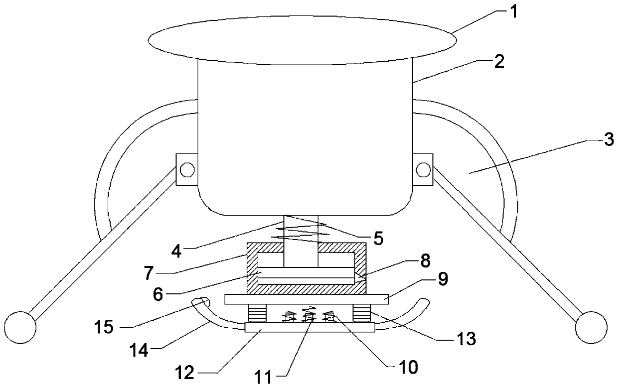
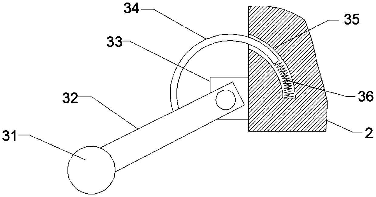
[0022] see Figure 1-Figure 2 The landing buffer device for a drone shown includes a drone body 1, a frame 2 and an auxiliary buffer mechanism 3, the frame 2 is fixedly arranged on the lower end surface of the drone body 1, and the auxiliary The buffer mechanism 3 is arranged on the side of the frame 2, and the auxiliary buffer mechanism 3 includes a support cylinder 31, a support rod 32, a connecting ear 33, an arc guide rod 34, an arc guide groove 35 and a d...


PUM


Abstract

The invention discloses a landing buffering device for an unmanned aerial vehicle. The landing buffering device for the unmanned aerial vehicle comprises an unmanned aerial vehicle body, a frame and auxiliary buffering mechanisms, wherein the frame is fixedly arranged on the lower end surface of the unmanned aerial vehicle body; the auxiliary buffering mechanisms are arranged on one side of the frame; a carbon fiber pipe is fixedly arranged on the lower end surface of the frame; a first spring sleeves the carbon fiber pipe; an exhaust port is formed in one side of the bottom of an air cylinder; a mounting plate is fixedly arranged at the lower end of the air cylinder, and is connected with an undercarriage at the lower end through two crash boxes symmetrically arranged; the undercarriage is of an airbag structure; a cycle valve is fixedly arranged on one side of the undercarriage; three spring mounting seats are arranged on the undercarriage between the crash boxes; and second springs sleeve the spring mounting seats. The landing buffering device is simple and reasonable in structural design; and crash energy is consumed step by step when the unmanned aerial vehicle lands through a multi-stage damping component, the damping process is more stable, the buffering effect is good, the resilience is slow, the secondary damage is avoided, and the condition that the unmanned aerial vehicle sinks into rivers and lakes at failure can be avoided.

Description

technical field [0001] The invention relates to the technical field of drones, in particular to a landing buffer device for drones. Background technique [0002] At present, UAVs have been widely used in aerial remote sensing, meteorological research and agricultural aerial broadcasting, especially in war, they have special advantages and can be widely used in aerial reconnaissance, surveillance, communication, anti-submarine and electronic jamming, etc. However, in When using a UAV in the wild, due to the complex terrain, when the UAV lands on a complex ground, it is easy to land unstable and cause damage. Most of the existing UAVs do not have shock absorbers, and only a few use springs to absorb shocks. This will not only impact some important parts when landing, but also if the UAV lands too fast or falls out of control, it is easy to damage the landing gear or even the body, and the existing spring method will bounce violently after landing. Large, it is easy to cause s...

Claims


Application Information

Patent Timeline
Patent Type & Authority Applications(China)
IPC IPC(8): B64C25/04B64C25/58B64C25/62B64C25/64
CPCB64C25/04B64C25/58B64C25/62B64C25/64
Inventor 吴佩雷斯国立
Owner 智飞智能装备科技东台有限公司
Why Eureka
Try Eureka