Concrete pouring device and pouring method

A concrete and mounting frame technology, which is applied in construction, building structure, and building material processing, etc., can solve the problems of inaccurate control of vibration accuracy and speed, heavy manual labor, and low vibration efficiency.

Active Publication Date: 2021-06-04
上海知碳电力工程有限公司
View PDF0 Cites 0 Cited by
  • Summary
  • Abstract
  • Description
  • Claims
  • Application Information

AI Technical Summary

Problems solved by technology

Among them, tamping is also called "vibration". When vibrating, workers usually need to use a plug-in vibrator to vibrate. The insertion points should be evenly arranged, moved point by point, and carried out in sequence to achieve uniform vibration. The amount of labor involved is large, and manual vibration is dangerous, and the precision and speed of controlling the vibration are not accurate, and the vibration efficiency is low when the vibration position is long.

Method used


Image

  • Concrete pouring device and pouring method
  • Concrete pouring device and pouring method
  • Concrete pouring device and pouring method

Examples


specific Embodiment approach 1

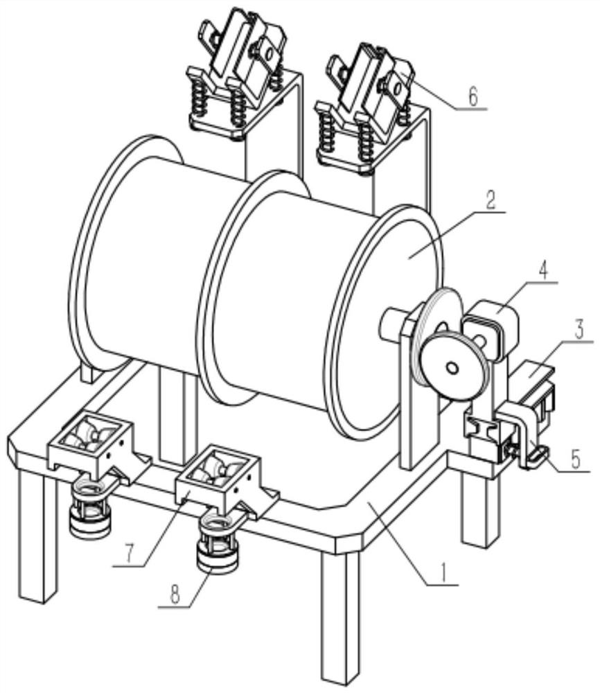
[0034] Such as Figure 1-10 As shown, a concrete pouring device includes a movable frame 1, a retractable roller 2, a variable speed carrier 3, a displacement power source 4, a positioner 5, a vibration-damping mounting frame 6, a first guide 7 and a second Two guides 8, the middle part of the movable frame 1 is rotatably connected to the retractable roller 2, the variable speed carrier 3 is fixedly connected to the movable frame 1, the displacement power source 4 is slidably connected to the variable speed carrier 3, and the variable speed carrier 3 is adjusted. The positioner 5 is fixedly connected to the displacement power source 4, the positioner 5 is engaged with the speed change carrier 3, the vibration-damping mounting frame 6 is fixedly connected to the front side of the movable frame 1, and the first guide 7 is connected to the movable The rear side of the frame 1 is fixedly connected, and the second guide 8 is fixedly connected to the lower end of the first guide 7 ....

specific Embodiment approach 2

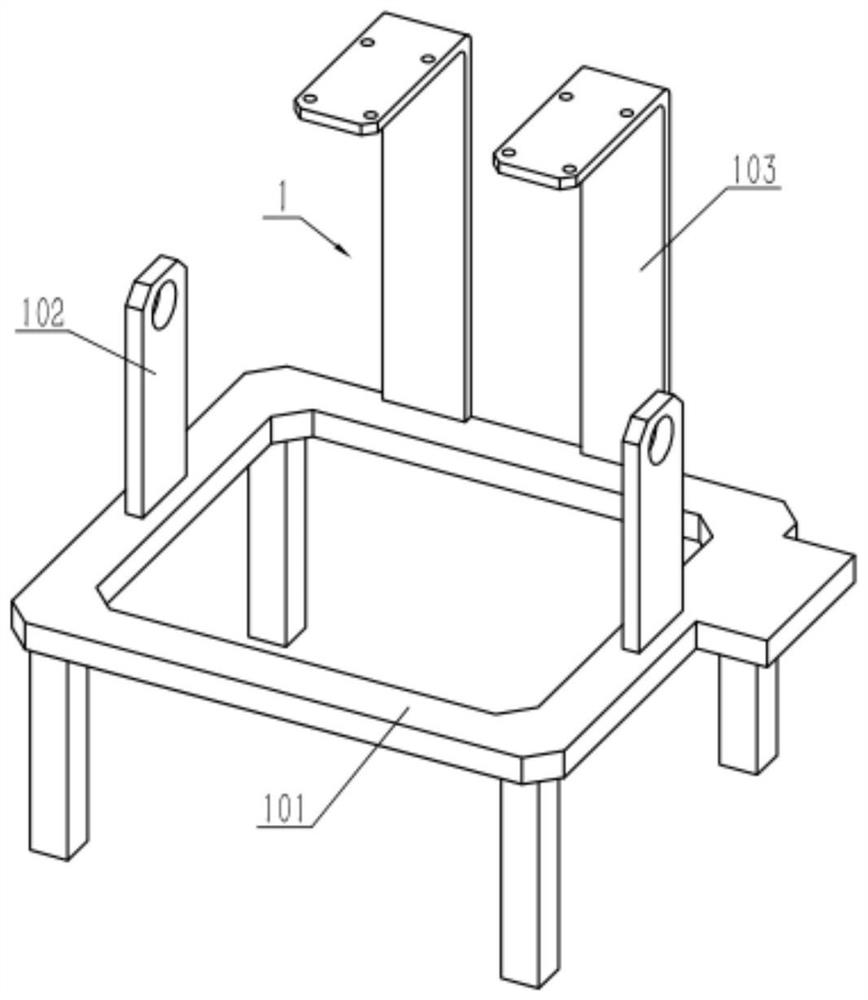
[0036] Such as Figure 1-10 As shown, the movable frame 1 includes a frame main body 101, a bearing with a seat 102 and a vibrator carrier 103, and the left and right sides of the middle part of the frame main body 101 are respectively fixedly connected with a bearing with a seat 102, and the vibrator is carried The frame 103 is fixedly connected to the front side of the frame main body 101 . Bearing with seat 102 is used for installing retractable roller 2, and vibrator carrier frame 103 is used for installing damping installation frame 6, refer to figure 1 , according to needs, the present invention can be set to different specifications, that is, to increase the number of vibration machine carriers 103, and correspondingly increase the number of first guides 7 and second guides 8, and the lower end of the frame body 101 can pass through Install on wheels or set up on mobile equipment to move.

specific Embodiment approach 3

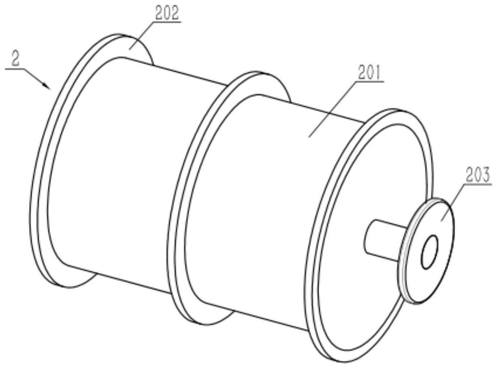
[0038] Such as Figure 1-10 As shown, the retractable roller 2 includes a retractable roller body 201, a partition ring 202 and a first friction disc 203, at least two partition rings 202 are fixedly connected to the retractable roller body 201, and the first friction disc 203 is fixedly connected On the main shaft at the right end of the retractable roller body 201 ; When the vibrator of the plug-in vibrator is wound up on the roll body 201, the position is restricted by two spacer rings 202, refer to image 3 At this time, there are three separating rings 202, and the vibrating rods of two plug-in vibrators can be rolled up on the retractable roller body 201, so that multiple vibrating rods can be inserted into the concrete at the same time as required.


PUM


Abstract

The invention relates to the field of construction, more specifically a concrete pouring device and a pouring method, including a movable frame, retractable rollers, a variable speed carrier, a displacement power source, a position adjuster, a vibration damping mounting frame, a first The guide and the second guide can adjust the contact position between the second friction disc and the first friction disc through the combined use of the variable speed carrier, the displacement power source and the positioner, so that the operator can quickly vibrate according to the pouring requirements. Adjust the retracting speed of the vibrating rod; through the first guide and the second guide, the vibrating rod can move up and down stably when retracting, and the concrete on the vibrating rod can be automatically removed when the vibrating rod is recovered. Avoid that the concrete piled up on the vibrating rod affects the present invention to vibrate at the next position.

Description

technical field [0001] The invention relates to the field of construction, in particular to a concrete pouring device and a pouring method. Background technique [0002] Concrete pouring is the construction process of pouring the mixed concrete material into the warehouse, closing the warehouse, and tamping and compacting. Among them, tamping is also called "vibration". When vibrating, workers usually need to use a plug-in vibrator to vibrate. The insertion points should be evenly arranged, moved point by point, and carried out in sequence to achieve uniform vibration. The amount of labor involved in pounding is large, and manual shaking is dangerous, the precision and speed of controlling the shaking are not accurate, and the shaking efficiency is low when there are many shaking positions. Contents of the invention [0003] The object of the present invention is to provide a concrete pouring device, which can realize accurate vibrating position, can quickly adjust the re...

Claims


Application Information

Patent Timeline
Patent Type & Authority Patents(China)
IPC IPC(8): E04G21/02E04G21/08
CPCE04G21/02E04G21/08
Inventor 万辉
Owner 上海知碳电力工程有限公司
Why Eureka
Try Eureka