
An intelligent monitoring device without monitoring blind spots

A technology of intelligent monitoring and equipment, applied in the direction of mechanical equipment, color TV parts, TV system parts, etc., can solve the problems of limited rotation angle of the camera, the camera cannot be pulled in, and the details are not easy to see clearly, etc., to solve the problem of rotation The effect of limited angle, comprehensive monitoring, and free adjustment angle

Active Publication Date: 2020-11-03
桐乡市定邦信息技术有限公司
View PDF13 Cites 0 Cited by
  • Summary
  • Abstract
  • Description
  • Claims
  • Application Information

AI Technical Summary

Problems solved by technology

However, the rotation angle of the camera of the monitoring device is limited, and the camera of the monitoring device cannot be pulled into the distance from the object, so it is difficult to see clearly when monitoring some details

Method used


Image

  • An intelligent monitoring device without monitoring blind spots
  • An intelligent monitoring device without monitoring blind spots
  • An intelligent monitoring device without monitoring blind spots

Examples


specific Embodiment approach 1

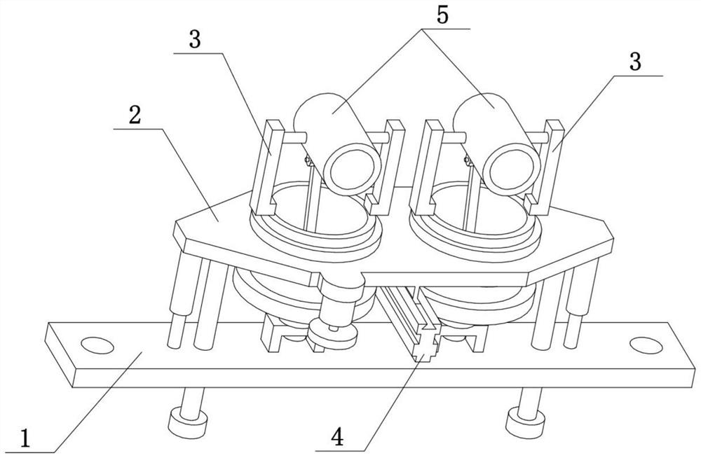
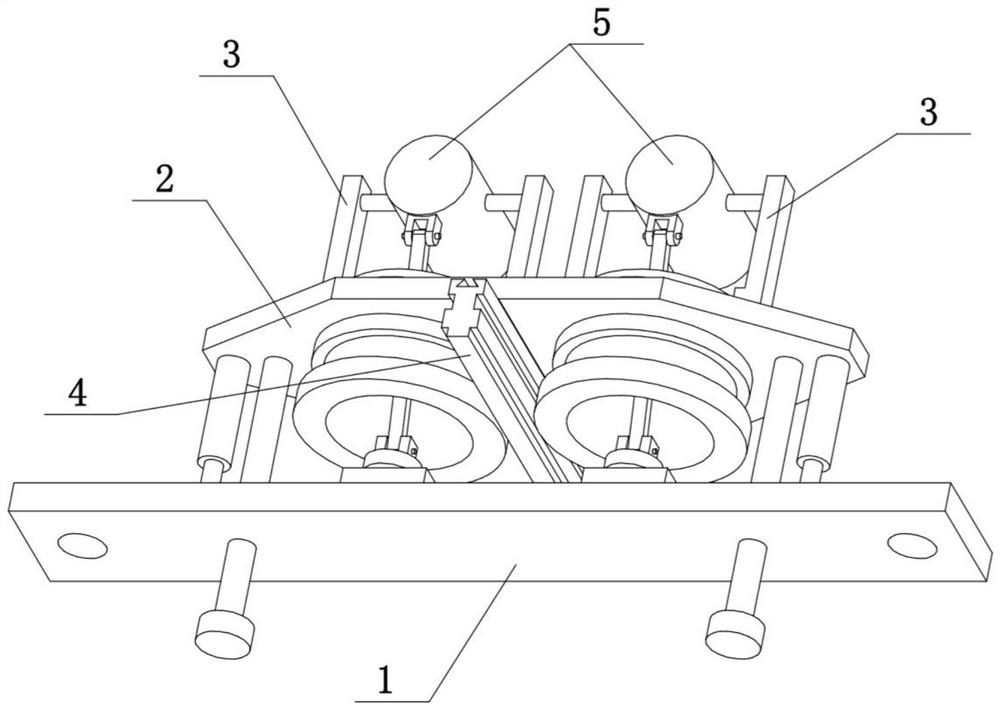
[0032] Combine below Figure 1-10 To illustrate this embodiment, the present invention relates to a monitoring device, more specifically an intelligent monitoring device without a monitoring blind area, including a fixed seat 1, a main frame body 2, a turret 3, a transmission member 4 and a monitor 5, The wide-angle camera seat 5-1 can rise while lifting, narrowing the bureau distance between the wide-angle camera and the high place object, and monitoring the high place more clearly. The wide-angle camera seat 5-1 can be lowered while inclining downwards, to draw in the local distance with the low objects, and monitor the low positions more clearly.

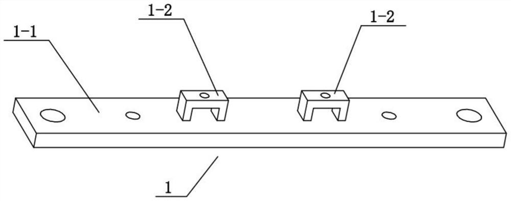
[0033] The fixed seat 1 includes a flat strip 1-1 and a door-shaped seat 1-2, and the upper end of the flat strip 1-1 is symmetrically arranged with two door-shaped seats 1-2; The board 1-1 is fixed in a certain position.

[0034] The main frame body 2 includes a flat wide plate 2-1, a circular through hole 2-2, an electric tel...

specific Embodiment approach 2

[0039] Combine below Figure 1-10 To illustrate this embodiment, the left and right ends of the flat strip 1-1 are provided with screw insertion holes. The screw sockets are used to insert screws, and then the flat strip 1-1 is fixed at a certain position.

specific Embodiment approach 3

[0041] Combine below Figure 1-10 To illustrate this embodiment, the main frame body 2 also includes a gear 2-6 and a motor 2-7, the front end of the flat wide board 2-1 is fixedly connected to the motor 2-7, and the lower end of the motor 2-7 is fixedly connected to the output shaft Gear 2-6 is arranged, and gear 2-6 is meshed with one of the gear rings 3-3 for transmission. The motor 2-7 can drive the gear 2-6 to rotate, and the gear 2-6 drives one of the gear ring 3-3 and the cylinder 3-1 to rotate, and the gear ring 3-3 drives the other gear ring 3-3 and the cylinder 3-1 through the transmission part 4. The cylinders 3-1 rotate in opposite directions, realizing the rotation control of the two cylinders 3-1.


PUM


Abstract

The present invention relates to a monitoring device, more specifically an intelligent monitoring device without a monitoring blind spot. The seat of the wide-angle camera will rise while being raised, and the distance between the wide-angle camera and objects at a high place will be shortened, and the distance between the wide-angle camera and objects at a high place will be shortened. position for clearer monitoring. The wide-angle camera seat will be lowered while tilting downward, pulling in the local distance with low objects, and monitoring the low positions more clearly. The fixed seat includes a flat slat and a door-shaped seat, and two door-shaped seats are arranged symmetrically on the upper end of the flat slat; the main frame body includes a flat wide board, a circular through hole, an electric telescopic rod, a vertical round Rods, limiters and trapezoidal convex strips, the left and right ends of the flat wide plate are provided with circular through holes, the left and right ends of the lower end of the flat wide plate are fixedly connected with vertical round rods, and the lower ends of the two vertical round rods are fixed It is connected with the limit piece, the middle position of the lower end of the flat and wide board is provided with a trapezoidal convex strip, and the left and right ends of the lower end of the flat and wide board are fixedly connected with electric telescopic rods.

Description

technical field [0001] The invention relates to a monitoring device, in particular to an intelligent monitoring device without monitoring blind spots. Background technique [0002] Application number CN201621493028.4 discloses a remote monitor for jewelry anti-theft. This utility model provides a remote monitor for jewelry anti-theft. Its structure includes a monitor shell, a monitor angle adjustment knob, and a monitor rotation Support, camera, infrared device, monitor base, wireless transmitter base, antenna, the angle adjustment knob of the monitor is located on both sides of the monitor housing, the monitor rotating support is located under the monitor housing, the The camera is arranged on the surface of the monitor casing, the infrared device is arranged on the surface of the monitor casing, the monitor base is arranged below the monitor rotating support, the wireless transmitter base is fixedly connected to the monitor base, and the antenna is set Above the base of t...

Claims


Application Information

Patent Timeline
Patent Type & Authority Patents(China)
IPC IPC(8): H04N7/18H04N5/225F16M11/24F16M11/06
CPCH04N7/18F16M11/24F16M11/06H04N23/50H04N23/45
Inventor 郭春龙
Owner 桐乡市定邦信息技术有限公司
Learn More