Supercharge Your Innovation With Domain-Expert AI Agents!

fiber optic cable

A technology of optical fiber cable and optical fiber, which is applied in the field of optical fiber cable, can solve the problems of large untwisting force and the inability of the optical fiber unit to keep being twisted, and achieve the effect of inhibiting movement

Active Publication Date: 2020-02-21
FUJIKURA LTD
View PDF9 Cites 0 Cited by
  • Summary
  • Abstract
  • Description
  • Claims
  • Application Information

AI Technical Summary

Problems solved by technology

And, if the optical fiber unit is moved in the sheath by the untwisting force, the optical fiber unit becomes unable to maintain the twisted state.
In addition, if a plurality of optical fiber units are accommodated in the sheath in a state twisted in an SZ shape, the untwisting force will also increase, and the above-mentioned movement of the optical fiber units will be more likely to occur.

Method used


Image

  • fiber optic cable
  • fiber optic cable

Examples


Embodiment Construction

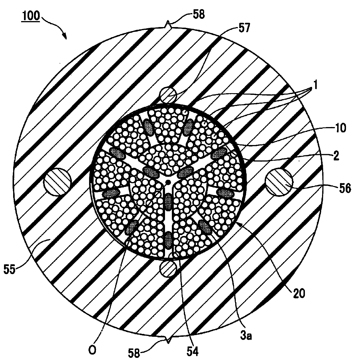
[0011] Below, refer to figure 1 The structure of the optical fiber cable according to this embodiment will be described.

[0012] In addition, in figure 1 Among them, the scale is appropriately changed according to the actual product so that the shape of each component can be recognized.

[0013] Such as figure 1 As shown, the optical fiber cable 100 includes: a core 20 having a plurality of optical fiber units 10; a sheath 55 that accommodates the core 20 inside; and a pair of tensile members 56 (tension members) embedded in the sheath 55 and a To line body 57.

[0014]

[0015] Here, in the present embodiment, the optical fiber unit 10 extends along the central axis O. As shown in FIG. The direction along the central axis O is referred to as the longitudinal direction. A section perpendicular to the central axis O of the optical fiber cable 100 is called a cross section.

[0016] In addition, in cross section ( figure 1 ), the direction intersecting the central axis...


PUM


Abstract

An optical fiber cable comprising: a core portion in which a plurality of optical fiber units each having a plurality of optical fibers and a fibrous fiber-shaped fiber unit extending along a longitudinal direction in which the optical fiber units extend are interposed by a pressurized winding portion; and a sheath, which accommodates the above-mentioned core inside; and a pair of tensile members, which are embedded in the above-mentioned sheath with the above-mentioned core being interposed. Let the total value of the cross-sectional area of ​​the optical fiber be Sf, let the total value of the cross-sectional area of ​​the above-mentioned inclusion be Sb, let the cross-sectional area of ​​the inner space of the above-mentioned sheath be Sc, and let the cross-sectional area of ​​the above-mentioned pressurized winding part be When Sw is used, it satisfies: 0.16≤Sb / Sf≤0.25 and 0.10≤Sb / (Sc-Sw)≤0.15.

Description

technical field [0001] The present invention relates to fiber optic cables. [0002] This application claims priority to Japanese Patent Application No. 2017-029056 filed in Japan on February 20, 2017, and its content is cited here. Background technique [0003] Conventionally, an optical fiber cable as disclosed in Patent Document 1 is known. This optical fiber cable includes: a buffer material arranged at a central portion; a plurality of optical fibers arranged around the buffer material; and a sheath that accommodates the buffer material and the plurality of optical fibers inside. Also, it is disclosed that with this structure, the external force applied to the optical fiber cable is absorbed by the buffer material, thereby preventing the optical fiber from being affected by the external force. [0004] Patent Document 1: Japanese Patent Laid-Open No. 2005-10651 [0005] However, in such an optical fiber cable, a plurality of optical fibers are bundled to form an opti...

Claims


Application Information

Patent Timeline
Patent Type & Authority Patents(China)
IPC IPC(8): G02B6/44
CPCG02B6/4411G02B6/443G02B6/44G02B6/4433
Inventor 梶智晃富川浩二大里健
Owner FUJIKURA LTD
Features
  • R&D
  • Intellectual Property
  • Life Sciences
  • Materials
  • Tech Scout
  • Unparalleled Data Quality
  • Higher Quality Content
  • 60% Fewer Hallucinations
Learn More