Steel-wire-rope traction device

A technology of traction device and wire rope, which is applied in the direction of winch device and spring mechanism, etc., can solve the problems of unfavorable device transfer and erection, increase the extra work of wire rope, and accelerate the loss of wire rope, etc., so as to improve operation efficiency, good versatility, Guaranteed smooth results

Pending Publication Date: 2019-09-24
XUANCHENG POWER SUPPLY COMPANY OF STATE GRID ANHUI ELECTRIC POWER +1
View PDF0 Cites 3 Cited by
  • Summary
  • Abstract
  • Description
  • Claims
  • Application Information

AI Technical Summary

Problems solved by technology

[0003] During the process of the steel wire rope pulling the carrying device, the steel wire rope is in a freely swinging friction state at the edge of the inspection well mouth, and the surface of the steel wire rope and the edge of the inspection well mouth will be damaged to varying degrees, which not only increases the manpower input during the traction process, but also affects The beauty of the manhole head speeds up the loss of the wire rope
The existing wire rope traction device is directly placed on the top edge of the port of the inspection well or is clamped to the edge of

Method used


Image

  • Steel-wire-rope traction device
  • Steel-wire-rope traction device
  • Steel-wire-rope traction device

Examples


Embodiment Construction

[0037] The preferred embodiments of the present invention will be described in detail below in conjunction with the accompanying drawings, so that the advantages and features of the present invention can be more easily understood by those skilled in the art, so as to define the protection scope of the present invention more clearly.

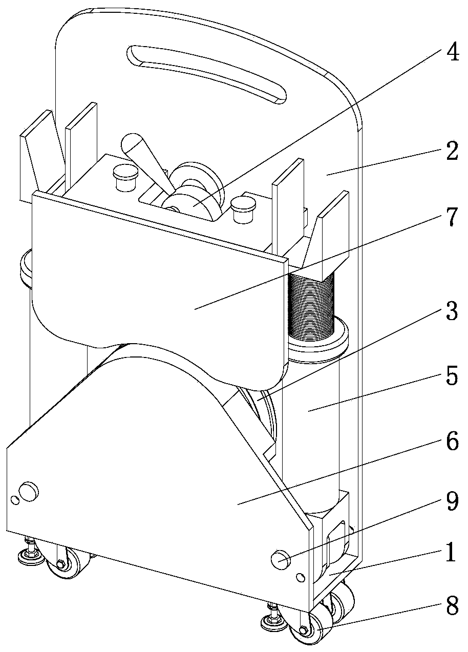
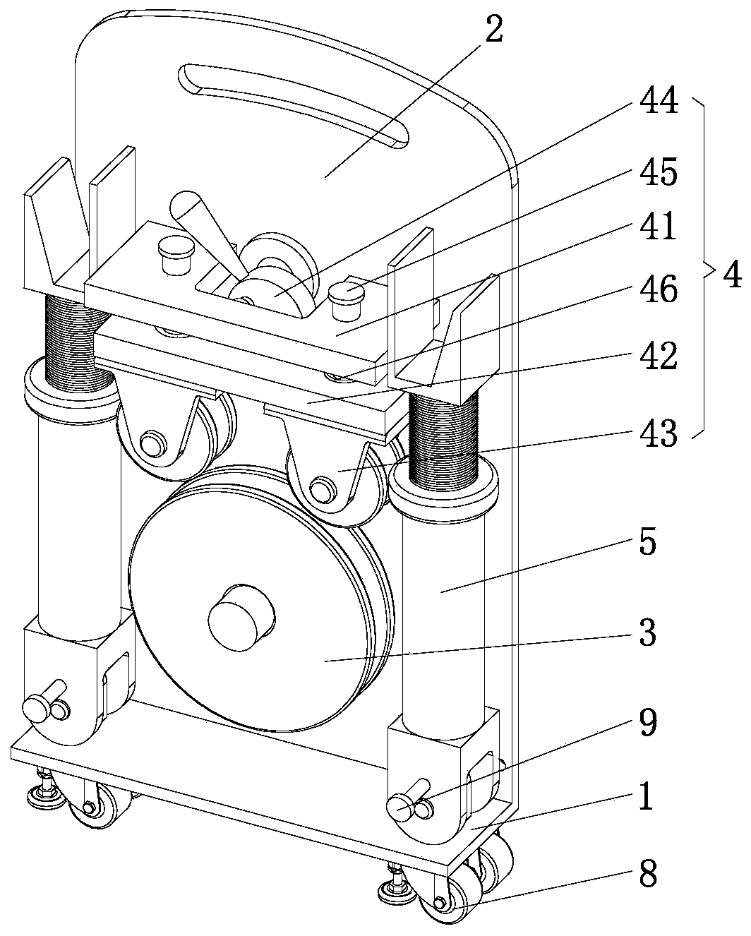
[0038] see figure 1 with figure 2 , a wire rope traction device, including a base plate 1, a mounting frame plate 2, a traction wheel 3, and a locking mechanism 4.

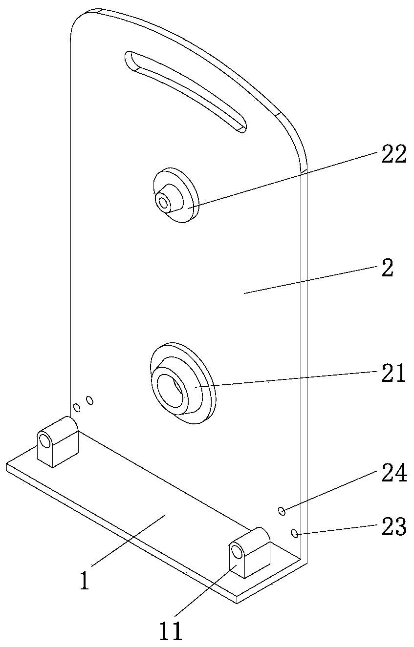
[0039] The mounting frame plate 2 is welded and fixed on one side of the top surface of the bottom plate 1 to form an L-shaped mounting frame. Such as image 3 As shown, a traction wheel mounting seat 21 is fixedly installed at the center of the side bottom of the mounting frame plate 2, and the shaft end of the traction wheel 3 is connected in the traction wheel mounting seat 21 through bearing rotation. The traction wheel 3 adopts an arc groove sheave mechanism, and the wire ro...


PUM


Abstract

The invention discloses a steel-wire-rope traction device which comprises a baseplate, a mounting frame plate, a traction wheel and a position-locking mechanism, wherein the mounting frame plate is fixed on one side of the top surface of the baseplate; the bottom of one side face of the mounting frame plate is rotationally connected with the traction wheel in which a steel wire rope is embedded; the position-locking mechanism for locking the position of the steel wire rope in the traction wheel is arranged over the traction wheel and fixed at the upper part of one side face of the mounting frame plate; two sides of the top face of the baseplate are respectively and rotationally connected with clamping assemblies located respectively on two sides of the traction wheel; and a plurality of wheels are mounted on the bottom face of the baseplate. According to the steel-wire-rope traction device, by arranging the position-locking mechanism over the traction wheel, the problem of the release of the steel wire rope from the traction wheel can be effectively avoided; the folding clamping assemblies provide convenience for the erection of the steel-wire-rope traction device on an inspection shaft and can meet the needs of clamping the steel-wire-rope traction device to inspection shaft lids of different types and specifications, so that the steel-wire-rope traction device has wide application range and good universality; and the steel-wire-rope traction device is compact in overall structure, small in size, and convenient to carry and move.

Description

technical field [0001] The invention relates to engineering construction tooling, in particular to a wire rope traction device. Background technique [0002] In places such as turnings, branches, and drops of municipal drainage pipes, as well as in the laying area of ​​underground communication cables, inspection wells are usually set so that maintenance personnel can enter the pipeline for maintenance. During the maintenance process, for the clogged pipelines, manual and hydraulic dredging are currently mainly used to clean them. During the cleaning process of bricks, stones, some silt and other residues in the well, these residues need to be transferred by the carrying device, and the movement of the carrying device is usually pulled by a wire rope that penetrates from the inspection well mouth, and the wire rope is pulled by manpower to move . [0003] During the process of the steel wire rope pulling the carrying device, the steel wire rope is in a freely swinging fric...

Claims


Application Information

Patent Timeline
IPC IPC(8): B66D1/28B66D1/36
CPCB66D1/28B66D1/36
Inventor 徐斌金卫董思锋傅冬生赵敏吕冰马玉徐昌凤孙天轮
Owner XUANCHENG POWER SUPPLY COMPANY OF STATE GRID ANHUI ELECTRIC POWER
Why Eureka
Try Eureka