Communication method and device of terminal and base station and network access method and device of terminal
A communication method and terminal technology, applied in the field of communication, can solve problems such as terminal failure to access, channel usage scheme incompatibility, etc.
Active Publication Date: 2019-09-24
ALIBABA GRP HLDG LTD
2 Cites 0 Cited by
AI-Extracted Technical Summary
Problems solved by technology
However, due to the different channel usage schemes adopted by various manufacturers, it is incompatible with...
Abstract
The embodiment of the invention provides a communication method and device of a terminal and a base station and a network access method and device of the terminal, and the communication method of the terminal and the base station comprises: the terminal sending a first message to the base station through a first channel, the first message being used for requesting to access a network, and the first channel being in a first channel set; the terminal receiving a second message from a first base station through a second channel, the second message comprising at least one piece of channel scheme information, the channel scheme information being used for determining a first network connection scheme, and the second channel being in the first channel set; and the terminal determining a first network connection scheme according to the channel scheme information, and accessing a network through a second base station according to the first network connection scheme. In the embodiment of the invention, the channel use scheme of the base station is obtained through the signaling interaction in the terminal network access process, so that whether the network can be accessed or not is judged, and the network access process of the terminal is completed. And the interaction efficiency between the terminal and the base station is improved.
Application Domain
Assess restrictionConnection management
Technology Topic
Base stationAccess method +2
Image
Examples
- Experimental program(1)
Example Embodiment
[0093] In order to make the above objectives, features and advantages of the application more obvious and understandable, the application will be further described in detail below in conjunction with the drawings and specific implementations.
[0094] The LoRa network is composed of terminal nodes, base station nodes and servers. In the embodiment of the solution of the present invention, the server may also be called a network server. The terminal has LoRa network connection capability and accesses the LoRa network. According to the different application scenarios deployed by the LoRa network, the terminal may include different electronic devices. For example, when the LoRa network is used in urban management, the terminal may include a smart meter; when the LoRa network is used in digital homes At the time, the terminal can include various smart home appliances and so on.
[0095] The base station, also known as the gateway or concentrator in the LoRa network, has the function of wireless connection convergence, including the terminal providing access to the LoRa network, forwarding the data from the server or terminal, and realizing the data between the terminal and the server Interactive. Of course, the base station can also exchange data with other base stations within the signal coverage area of the base station by transmitting wireless frames.
[0096] The server may include a server or server cluster, which is used to perform service processing according to data obtained from the base station or terminal, and to control the working mode and working state of the base station or the terminal.
[0097] One of the core concepts of the embodiments of the present application is that the terminal learns the channel usage plan of the base station through network access signaling, so as to determine whether the same channel usage plan can be used to access the network.
[0098] Below, firstly, the communication process between the terminal and the base station is introduced from the perspective of the terminal.
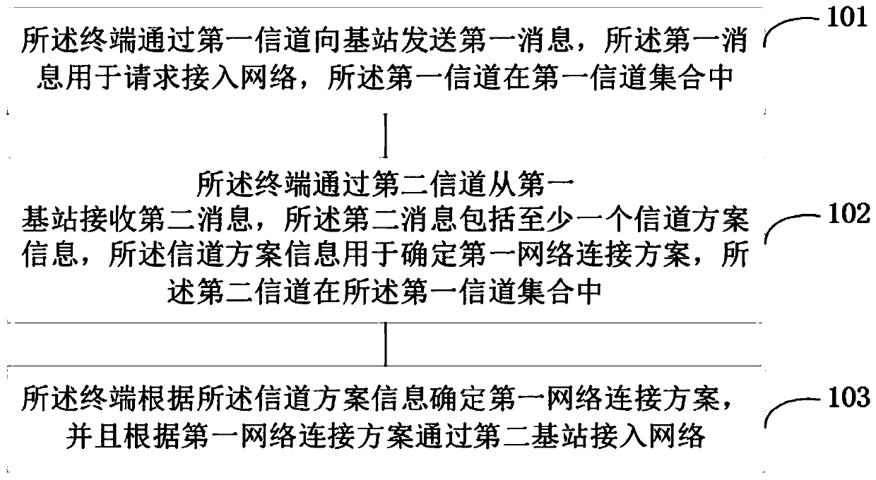
[0099] Reference figure 1 , Shows a step flow chart of Embodiment 1 of a communication method between a terminal and a base station of the present application, which may specifically include the following steps:
[0100] Step 101: The terminal sends a first message to a base station through a first channel, where the first message is used to request access to a network, and the first channel is in a first channel set;
[0101] Specifically, the first channel may be a known uplink connection channel (join channel). The first message may be a join request message. The terminal sends a connection request to the base station through a known connection channel. The first channel set may be one of a common join channel set (common join channel) preset between the terminal and the base station. The connection request sent by the terminal will be received by one or more base stations, and sent to the server through the one or more base stations. After that, the first base station sends the join-accept information to the terminal. The first base station may be among the one or more base stations, or may not be among the one or more base stations, which is not specifically limited in the present invention. Connection acceptance information can also be called network access acceptance information, or network access acceptance frame;
[0102] In the embodiment of the present application, a common connection channel set is set between the terminal and the base station, and the terminal can send a connection request to the base station through the common connection channel set.
[0103] For example, in the LoRa spectrum, the connection channel can be selected as channel 3 (470.9) MHz, channel 11 (472.5MHz), channel 19 (474.1MHz), channel 27 (475.1MHz), channel 71 (484.5MHz), channel 79 (486.1MHz), channel 87 (478.7MHz), and channel 95 (489.3MHz). Among them, channels 3, 11, 19, and 27 are uplink connection channels. The remaining 5 are downlink connection channels. The uplink and downlink connection channels form a group in pairs, for example, channel 3 and channel 71 are a group of uplink and downlink connection channels. The terminal may send a join request (join request) message to the base station through channel 3, and obtain a join-accept message from channel 71.
[0104] In the embodiment of the present application, the step 101 may include the following sub-steps:
[0105] Sub-step S1011, if the terminal sequentially sends a first message to the base station through at least one third channel in the first channel set;
[0106] Specifically, the first channel set may be a common connection channel set. Because the terminal does not know the working channel information of the base station before connecting to the network. Therefore, the terminal can sequentially send connection requests through the uplink connection channels in the common connection channel set, and if the sent connection request does not receive a corresponding connection acceptance message, it sends the connection request to the base station through the next uplink connection channel. Until the connection acceptance message is received. For example, the terminal first sends a connection request message to the base station through the uplink connection channel 19, and after judging that the corresponding connection acceptance message is not received within a specified time, the terminal sends a connection request message to the base station through the uplink connection channel 19, and successfully The corresponding connection acceptance message was received within time. Then the terminal no longer sends a connection request message to the base station through the uplink connection channel 27. The third channel may be the first channel, or may be another channel different from the first channel in the first channel set.
[0107] In sub-step S1012, the terminal receives a second message sent by the first base station through a fourth channel, where the fourth channel is in the first channel set.
[0108] Specifically, the fourth channel may be the second channel. It may also be other downlink connection channels except the second channel in the common connection channel set. The second message is a connection acceptance message.
[0109] Step 102: The terminal receives a second message from the first base station through a second channel, the second message includes at least one channel plan information, the channel plan information is used to determine a first network connection plan, and the second channel In the first channel set;
[0110] Specifically, the first channel may be a known downlink connection channel (join channel). The second message may be a join-accept message. The channel plan information may also be a channel plan ID (channel planID). A channel plan information represents a network connection plan. The network connection plan specifies the channel usage plan under the spectrum range. Channel planning includes the division of all channels within the spectrum (central frequency point, channel width, etc.), regulations on the use of uplink and downlink of channels, trial regulations on special channels, and various other conventions on the spectrum. There can be overlapping use parts between the set of connection channels and the network connection scheme, or they can be completely separated. The channel plan information can be letters or numbers, or can be expressed in mask form. The channel plan information may be carried by the channel frequency list (CFList) in the connection acceptance information. The channel frequency list may carry one channel plan information or multiple channel plan information, which is not specifically limited in the present invention. Optionally, the channel frequency list may include a set of channel plan information and a corresponding channel mask (Channel mask), or may include multiple sets of channel plan information and a corresponding channel mask. For example, the CFList may include channel plan id1, channel mask1, channel plan id2, channel mask2, channel plan id3, and channel mask3.
[0111] In the embodiment of the present application, step 101 or step 102 may include the following sub-steps:
[0112] Sub-step S1021, the terminal presets at least one network connection scheme and channel scheme information corresponding to the at least one network connection scheme;
[0113] Specifically, the network connection scheme refers to a channel usage plan under a certain spectrum range. Channel planning includes the division of all channels within the spectrum (central frequency point, channel width, etc.), regulations on the use of uplink and downlink of channels, trial regulations on special channels, and various other conventions on the spectrum. The channel plan information may also be a channel plan ID (channel plan ID). A channel plan information represents a network connection plan. For example, the channel plan identifier 1 may indicate a channel planning plan under 20 MHz. The channel plan identifier 2 can identify the channel planning plan under 30 MHz. In this embodiment, the number of the channel plan identifier is only used as an example, and the present invention does not specifically limit it.
[0114] In the embodiment of the present application, step 101 or step 102 may include the following sub-steps:
[0115] In sub-step S1022, the second message further includes a channel mask, and the channel mask is used to map the first channel subset of the first network connection scheme;
[0116] Specifically, a channel mask (Channel Mask) refers to a string of binary codes (or strings) that can be one-to-one corresponding to each channel or channel subset. The channel mask can indicate whether this channel or a subset of channels is currently available. The channel mask can be sent to the terminal as a part of the channel frequency list (CFList) field in the connection acceptance message. The terminal can obtain the channel mask from the first base station, and calculate the uplink and downlink data channels that can interact with the second base station. The first channel itself can be an uplink and downlink data channel calculated through a channel mask that can interact with the second base station. The first base station deploys part or all of the channels of the first channel set. The second base station deploys some or all of the channels in the first network connection scheme. The first base station and the second base station may be on the same physical base station or not on the same physical base station, which is not specifically limited in the present invention. The base station can also be a gateway (Gateway).
[0117] Sub-step S1023, the terminal determines the first channel subset according to the channel plan information and the channel mask, and accesses the network through a second base station according to the first channel subset;
[0118] Specifically, the terminal may obtain the corresponding channel planning scheme through the channel plan ID (Channel plan ID). And the uplink and downlink data channels that can interact with the base station can be obtained through the channel mask, and the uplink data packet can be sent to the base station through the uplink channel.
[0119] In the embodiment of the present application, step 101 or step 102 may include the following sub-steps:
[0120] In sub-step S1024, the second message further includes at least one channel plan information mask, and the channel plan information mask is used to map at least one first network connection plan;
[0121] Specifically, the channel plan information mask (channel plan id mask) can replace the channel plan information (channel plan id) to characterize a specific first network connection plan. For example, bit1 represents network connection plan 1, bit2 represents network connection plan 2, and so on. The second message may be join-accept information. The connection acceptance information may carry one channel plan information mask or multiple channel plan information masks, and the scheme of the present invention is not specifically limited.
[0122] Step 103: The terminal determines a first network connection scheme according to the channel scheme information, and accesses the network through a second base station according to the first network connection scheme;
[0123] Specifically, after obtaining the channel plan information, that is, the channel plan identifier, the terminal finds the corresponding network connection plan. The terminal sends uplink data through the uplink channel specified in the network connection plan, and receives the downlink data packet sent by the base station according to the calculated receiving window.
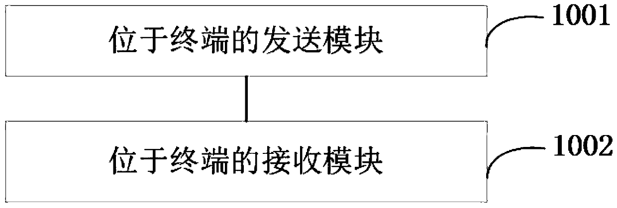
[0124] Reference figure 2 , Shows a structural block diagram of Embodiment 2 of a communication device between a terminal and a base station of the present application, which may specifically include the following modules:
[0125] The sending module 1001 located in the terminal is configured to send a first message to the base station through a first channel, the first message is used to request access to the network, and the first channel is in a first channel set;
[0126] The receiving module 1002 located in the terminal is configured to receive a second message from the base station through a second channel, the second message includes at least one channel plan information, and the channel plan information is used to determine a first network connection plan. The second channel is in the first set of channels.
[0127] The sending module 1001 located in the terminal is further configured to determine a first network connection scheme according to the channel scheme information, and access the network through the second base station according to the first network connection scheme.
[0128] In the embodiment of the present application, the device may further include:
[0129] The sending module located in the terminal is configured to send the first message to the base station through at least one third channel in the first channel set in sequence;
[0130] The receiving module located in the terminal is configured to receive the second message sent by the first base station through a fourth channel, and the fourth channel is in the first channel set.
[0131] In the embodiment of the present application, the device may further include:
[0132] The terminal presets at least one network connection scheme and channel scheme information corresponding to the at least one network connection scheme;
[0133] In the embodiment of the present application, the device may further include:
[0134] The second information further includes a channel mask, and the channel mask is used to map the first channel subset of the first network connection scheme;
[0135] The terminal determines the first channel subset according to the channel plan information and the channel mask, and accesses the network through the second base station according to the first channel subset.
[0136] In the embodiment of the present application, the device may further include:
[0137] The second information further includes at least one channel plan information mask, and the channel plan information mask is used to map at least one first network connection plan;
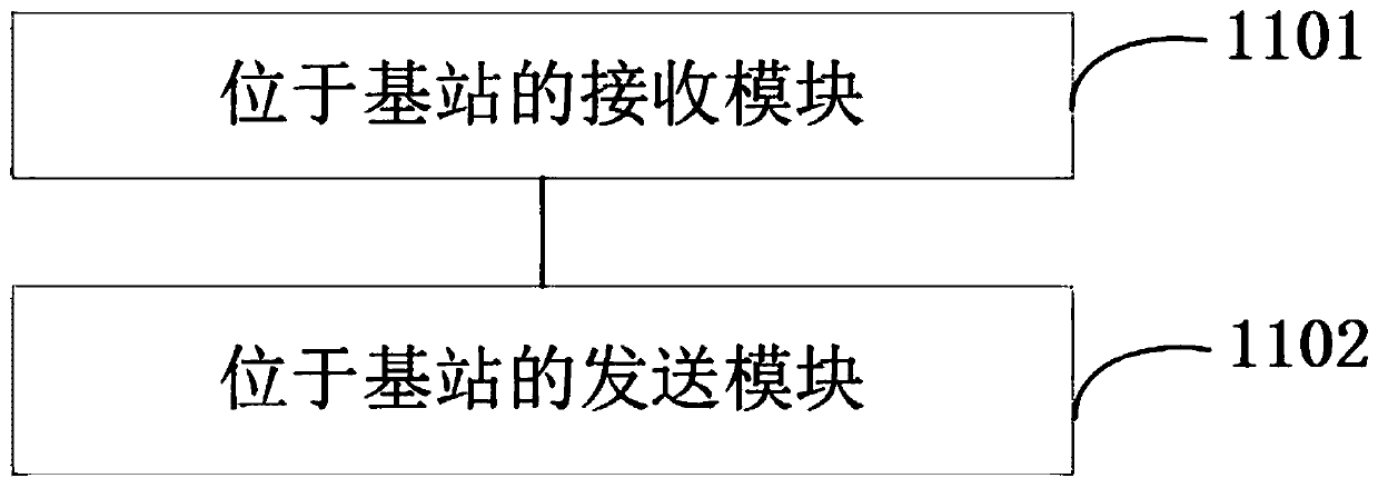
[0138] Reference image 3 , Shows a structural block diagram of Embodiment 3 of a communication device between a terminal and a base station of the present application, which may specifically include the following modules:
[0139] The receiving module 1101 located in the base station is configured to receive a first message sent by the terminal through a first channel, the first message is used to request access to the network, and the first channel is in a first channel set;
[0140] The sending module 1102 located in the base station is configured to send a second message to the terminal through a second channel, the second message includes at least one channel plan information, and the channel plan information is used to determine a first network connection plan. The second channel is in the first channel set.
[0141] In the embodiment of the present application, the device may further include:
[0142] The receiving module located in the base station is configured to sequentially receive the first information sent by the terminal through at least one third channel in the first channel set;
[0143] The sending module located in the base station is configured to send second information to the terminal through a fourth channel, where the fourth channel is in the first channel set.
[0144] In the embodiment of the present application, the device may further include:
[0145] The second information further includes a channel mask used to map the first channel subset of the first network connection scheme.
[0146] In the embodiment of the present application, the device may further include:
[0147] The second information further includes at least one channel plan information mask, and the channel plan information mask is used to map at least one first network connection plan;
[0148] Reference Figure 4 , Shows a step flowchart of Embodiment 1 of a communication method between a terminal and a base station according to the present application, which may specifically include the following steps:
[0149] Step 401: The terminal sends a first message to a base station through a first channel, the first message is used to request access to the network, the first channel is in a first channel set, and the first channel is used to indicate A network connection plan;
[0150] Specifically, the first channel may be a known uplink connection channel (join channel). The first message may be a join request message. The terminal sends a connection request to the base station through a known connection channel. The first channel set may be one of a common join channel set (common join channel) preset between the terminal and the base station. The connection request sent by the terminal will be received by one or more base stations, and sent to the server through the one or more base stations. After that, the first base station sends the join-accept information to the terminal. The first base station may be among the one or more base stations, or may not be among the one or more base stations, which is not specifically limited in the present invention. The first channel can be used to indicate the first network connection scheme. For example, uplink connection channel 1 indicates or represents network connection scheme one, and uplink connection channel 11 indicates or represents network connection scheme two. Multiple uplink connection channels can indicate the same network connection scheme. For example, the uplink connection channels 1-4 may all indicate or represent the network connection scheme 1 one. Among them, the first channel may also be the second channel. That is, the first channel and the second channel may be the same channel. For example, when the terminal is operating in the time division duplex mode, one channel can be used as an uplink connection channel and a downlink connection channel at the same time.
[0151] Step 402: The terminal receives a second message from the first base station through a second channel, the second message is used to make the terminal determine the first network connection scheme according to the first channel, and the second channel In the first channel set;
[0152] Specifically, the first channel may be a known downlink connection channel (join channel). The second message may be a join-accept message. The network connection plan specifies the channel usage plan under the spectrum range. Channel planning includes the division of all channels within the spectrum (central frequency point, channel width, etc.), regulations on the use of uplink and downlink of channels, trial regulations on special channels, and various other conventions on the spectrum. There can be overlapping use parts between the set of connection channels and the network connection scheme, or they can be completely separated. After the terminal receives the connection acceptance message through the downlink connection channel, it can determine its own network connection scheme according to the network connection scheme indicated by the corresponding uplink connection channel. If the terminal does not receive the corresponding connection acceptance message on the corresponding downlink connection channel after sending the first message through an uplink connection channel, it will continue to send the first message on the next uplink connection channel. The selection of the next uplink connection channel may be random selection in the first channel set or sequential selection.
[0153] Step 403: The terminal accesses the network through the second base station according to the first network connection scheme.
[0154] Specifically, after obtaining the join-accept message, the terminal can determine the corresponding network connection scheme according to the network connection scheme indicated by the uplink connection channel corresponding to the downlink connection channel. The terminal sends uplink data through the uplink channel specified in the network connection plan, and receives the downlink data packet sent by the base station according to the calculated receiving window.
[0155] Reference Image 6 , Shows a step flowchart of Embodiment 5 of a communication method between a terminal and a base station according to the present application, which may specifically include the following steps:
[0156] Step 501: The terminal sends a third message to at least one third base station through a third channel, the third message is used to request access to the network, and the third channel is included in at least one second network connection scheme;
[0157] Specifically, the third channel may be a known uplink connection channel (join channel). The third message may be a join request message. The terminal sends a connection request to the base station through a known connection channel. The connection request sent by the terminal will be received by one or more third base stations, and sent to the server through the one or more third base stations. After that, the fourth base station sends the join-accept information to the terminal. The fourth base station may be among the one or more third base stations, or may not be among the one or more base stations, which is not specifically limited in the present invention. The network connection plan specifies the channel usage plan under the spectrum range. Channel planning includes the division of all channels within the spectrum (central frequency point, channel width, etc.), regulations on the use of uplink and downlink of channels, trial regulations on special channels, and various other conventions on the spectrum. Different countries or regions can adopt different spectrum schemes according to different spectrum resources. For example, the China 920 spectrum plan (CN920) and the Australia 923 spectrum plan (AS923) can both be the second network connection plan. China 920 spectrum plan (CN920) can use 920 megahertz (MHz)-925 megahertz (MHz) spectrum resources. Australia 923 spectrum plan (AS923) can use 923-923.5MHz spectrum resources. The channel corresponding to the 923.2MHz frequency point can be included in both the 920 spectrum plan in China and the 923 spectrum plan in Australia.
[0158] In the embodiment of the present application, the step 501 may include the following sub-steps:
[0159] Sub-step S5011, the third channel is included in a second channel set;
[0160] Specifically, the third channel may be a known uplink connection channel (join channel). The second channel set may be a common join channel set (common join channel) preset between the terminal and the base station. The third channel may be included in the common connection channel set. For example, the channel corresponding to 923.2MHz is included in the AS923 and CN920 spectrum schemes. The channel corresponding to 923.2MHz can be included in the common connection channel set.
[0161] Step 502: The terminal receives a fourth message from a fourth base station through a fourth channel, the fourth message includes a channel plan identifier, and the fourth message is used to enable the terminal to determine the first message according to the channel plan identifier. Three network connection solutions, the fourth channel is included in the second channel set, the fourth channel is included in at least one second network connection solution, and the third network connection solution is included in the second network In the connection plan;
[0162] Specifically, the fourth channel may be a known downlink connection channel (join channel). The fourth message may be a join-accept message. The second channel set may be a common join channel set (common join channel) preset between the terminal and the base station. The second channel set may include at least one connection channel in all regional spectrum schemes. For example, the second channel set may include one connection channel in each of the AS923 and CN920 spectrum schemes. Wherein, the connection channel may also be a channel where multiple spectrum schemes overlap. For example, the connection channel corresponding to 923.2MHz is included in both the AS923 spectrum scheme and the CN920 spectrum scheme in the second channel set. The aforementioned downlink connection channel is included in the common connection channel set. The downlink connection channel may be included in multiple second network connection schemes, that is, multiple spectrum schemes. For example, as described in step 501, the channel corresponding to the 923.2 MHz frequency point may be included in both the 920 spectrum plan in China and the 923 spectrum plan in Australia. There may be overlapping use parts between the set of connection channels and the set of channels specified in the network connection plan, or they may be completely separated.
[0163] The connection acceptance message received by the terminal through the downlink connection channel may also be called a connection acceptance frame. The connection acceptance frame carries a channel plan ID (channel plan ID). The channel plan identifier can be placed at the end of the connection acceptance frame. This can make the channel plan identification easier to analyze. Figure 5 Shows the frame format of the connection acceptance frame. The channel plan identifier may follow the CFList field. If the terminal receives the connection acceptance frame, it uses the channel plan identifier carried in it to determine the spectrum plan used for subsequent communication with the network. When the frequency points corresponding to the downlink connection channel are included in multiple spectrum schemes, it is a more effective way to use the channel scheme identifier to determine the spectrum scheme used for subsequent communication with the network. For example, when the terminal moves to an area where both CN920 and AS923 spectrum schemes exist, the terminal cannot distinguish which scheme to follow based on the frequency corresponding to the downlink connection channel, because the CN920 and AS923 spectrum schemes are in the downlink connection channel. There is overlap on the corresponding frequency points. Therefore, the terminal can identify the scheme to be subsequently adopted according to the channel scheme identifier in the connection acceptance frame. For example, assuming that the channel plan ID is 1, it represents the CN920 spectrum plan, and the beacon plan ID is 2 it represents the AS923 spectrum plan. If the channel scheme identifier in the connection acceptance frame received by the terminal is 1, the terminal uses the CN920 spectrum scheme to communicate with the network side.
[0164] Optionally, there may also be channels included in only one network connection scheme in the common connection channel set. For example, the common connection channel set may include connection channels that access three network connection schemes. The three network connection schemes are CN920, AS923 and Russia 864-870MHz (RU864-870). The frequency point 868.9 MHz corresponding to the channel in the RU864-870 spectrum scheme is not included in CN920 and AS923. When the terminal receives a connection acceptance frame through the downlink channel corresponding to the frequency 868.9MHz, it can determine the frequency spectrum corresponding to the downlink channel to determine the spectrum scheme used for subsequent communication with the network side, or it can use the received connection acceptance frame The channel plan identifier is used to determine the spectrum plan used for subsequent communication with the network side. For example, the terminal judges that the frequency at which the connection acceptance frame is received is 868.9 MHz, and among all terminal-compatible network connection schemes, only RU864-870 supports 868.9 MHz. Therefore, the terminal determines that the spectrum scheme used for subsequent communication with the network is RU864-870. Or, suppose that the channel scheme ID corresponding to RU864-870 is 3. If the terminal receives the connection acceptance frame and analyzes that the channel scheme identifier carried in it is 3, it is determined that the spectrum scheme used for subsequent communication with the network is RU864-870. The third network connection scheme is for the terminal to determine the spectrum scheme used for subsequent communication with the network. The second network connection scheme may be a spectrum scheme supported by the terminal. The second connection scheme may also be a spectrum scheme that the terminal does not support. There can be multiple second network connection schemes. Multiple second network connection schemes may also form a network connection scheme set.
[0165] In the embodiment of the present application, the step 502 may include the following sub-steps:
[0166] In sub-step S5021, the terminal receives a fourth message from a fourth base station through a fourth channel, the fourth message includes a channel plan identifier and a network identifier, and the fourth message is used to make the terminal according to the channel plan identifier And the network identifier determines the third network connection scheme;
[0167] Specifically, the connection acceptance frame carries the network identification (Home_NetID). The network identification represents a unique identification of a LoRaWAN network. The terminal can know the spectrum scheme corresponding to the network identifier in advance. For example, if the terminal analyzes that the network identifier in the received connection acceptance frame is 51, it can determine that the corresponding spectrum scheme is the CN920 scheme. If the connection acceptance frame received by the terminal includes the network identification and the channel plan identification, the terminal determines the spectrum plan used for subsequent communication with the network according to the channel plan identification. If the connection acceptance frame received by the terminal only includes the network identification, the terminal determines the spectrum scheme used for subsequent communication with the network according to the network identification.
[0168] Step 503: The terminal accesses the network through the fifth base station according to the third network connection scheme.
[0169] Specifically, the third network connection scheme is for the terminal to determine a spectrum scheme used for subsequent communication with the network. The terminal sends uplink data through the uplink channel specified in the network connection plan, and receives the downlink data packet sent by the fifth base station according to the calculated receiving window. The fifth base station may also be the fourth base station.
[0170] In the embodiment of the present application, the step 502 may include the following sub-steps:
[0171] In sub-step S5031, the terminal may run in any fourth network connection scheme among the at least one second network connection scheme.
[0172] Specifically, the second network connection scheme may be a spectrum scheme supported by the terminal. There can be multiple second network connection schemes. A plurality of second network connection schemes may also form a network connection scheme set. The fourth connection scheme is any one of the second network connection schemes. For example, multiple second network connection schemes may include CN920, AS923, and RU864-870 spectrum schemes. The fourth connection scheme may be any one of the above three spectrum schemes.
[0173] Reference Figure 7 , Shows a step flow chart of Embodiment 6 of a communication method between a terminal and a base station of the present application, which may specifically include the following steps:
[0174] Step 601: The base station receives a third message sent by the terminal through a third channel, the third message is used to request access to the network, and the third channel is included in at least one second network connection scheme;
[0175] Specifically, the third channel may be a known uplink connection channel (join channel). The third message may be a join request message. The terminal sends a connection request to the base station through a known connection channel. The connection request sent by the terminal will be received by one or more third base stations, and sent to the server through the one or more third base stations. After that, the fourth base station sends the join-accept information to the terminal. The fourth base station may be among the one or more third base stations, or may not be among the one or more base stations, which is not specifically limited in the present invention. The network connection plan specifies the channel usage plan under the spectrum range. Channel planning includes the division of all channels within the spectrum (central frequency point, channel width, etc.), regulations on the use of uplink and downlink of channels, trial regulations on special channels, and various other conventions on the spectrum. Different countries or regions can adopt different spectrum schemes according to different spectrum resources. For example, the China 920 spectrum plan (CN920) and the Australia 923 spectrum plan (AS923) can both be the second network connection plan. The China 920 spectrum plan (CN920) can use 920 megahertz (MHz)-925 megahertz (MHz) spectrum resources. Australia 923 spectrum plan (AS923) can use 923-923.5MHz spectrum resources. The channel corresponding to the 923.2MHz frequency point can be included in both the 920 spectrum plan in China and the 923 spectrum plan in Australia.
[0176] In the embodiment of the present application, the step 601 may include the following sub-steps:
[0177] Sub-step S6011, the third channel is included in the second channel set;
[0178] Specifically, the third channel may be a known uplink connection channel (join channel). The second channel set may be a common join channel set (common join channel) preset between the terminal and the base station. The third channel may be included in the common connection channel set. For example, the channel corresponding to 923.2MHz is included in the AS923 and CN920 spectrum schemes. The channel corresponding to 923.2MHz may be included in the common connection channel set.
[0179] Step 602: The base station sends a fourth message to the terminal through a fourth channel, the fourth message includes a channel plan identifier, and the fourth message is used to enable the terminal to determine the first message according to the channel plan identifier. Three network connection solutions, the fourth channel is included in the second channel set, the fourth channel is included in at least one second network connection solution, and the third network connection solution is included in the second network Connection plan.
[0180] Specifically, the fourth channel may be a known downlink connection channel (join channel). The fourth message may be a join-accept message. The second channel set may be a common join channel set (common join channel) preset between the terminal and the base station. The aforementioned downlink connection channel is included in the common connection channel set. The downlink connection channel may be included in multiple second network connection schemes, that is, multiple spectrum schemes. For example, as described in step 501, the channel corresponding to the 923.2 MHz frequency point may be included in both the 920 spectrum plan in China and the 923 spectrum plan in Australia. There may be overlapping use parts between the set of connection channels and the set of channels specified in the network connection plan, or they may be completely separated.
[0181] The connection acceptance message received by the terminal through the downlink connection channel may also be called a connection acceptance frame. The connection acceptance frame carries a channel plan ID (channel plan ID). The channel plan identifier can be placed at the end of the connection acceptance frame. This can make the channel plan identification easier to analyze. Figure 5 Shows the frame format of the connection acceptance frame. The channel plan identifier may follow the CFList field. If the terminal receives the connection acceptance frame, it uses the channel scheme identifier carried in it to determine the spectrum scheme used for subsequent communication with the network. When the frequency points corresponding to the downlink connection channel are included in multiple spectrum schemes, it is a more effective way to use the channel scheme identifier to determine the spectrum scheme used for subsequent communication with the network. For example, when the terminal moves to an area where both the CN920 and AS923 spectrum schemes exist, the terminal cannot distinguish the subsequent scheme according to the frequency corresponding to the downlink connection channel, because the CN920 and AS923 spectrum schemes are in the downlink connection channel. There is overlap on the corresponding frequency points. Therefore, the terminal can identify the scheme to be subsequently adopted according to the channel scheme identifier in the connection acceptance frame. For example, assuming that the channel plan ID is 1, it represents the CN920 spectrum plan, and the beacon plan ID is 2 it represents the AS923 spectrum plan. If the channel scheme identifier in the connection acceptance frame received by the terminal is 1, the terminal uses the CN920 spectrum scheme to communicate with the network side.
[0182] Optionally, there may be channels included in only one network connection scheme in the set of common connection channels. For example, the set of common connection channels may include connection channels for access to three network connection schemes. The three network connection schemes are CN920, AS923 and Russia 864-870MHz (RU864-870). The frequency point 868.9MHz corresponding to the channel in the RU864-870 spectrum scheme is not included in CN920 and AS923. When the terminal receives the connection acceptance frame through the downlink channel corresponding to the frequency 868.9MHz, it can determine the spectrum scheme used for subsequent communication with the network side by the frequency corresponding to the downlink channel, or it can use the received connection acceptance frame in the The channel plan identifier is used to determine the spectrum plan used for subsequent communication with the network side. For example, the terminal determines that the frequency at which the connection acceptance frame is received is 868.9 MHz, and among all terminal-compatible network connection schemes, only RU864-870 supports 868.9 MHz. Therefore, the terminal determines that the spectrum scheme used for subsequent communication with the network is RU864-870. Or, suppose that the channel scheme ID corresponding to RU864-870 is 3. If the terminal receives the connection acceptance frame and parses that the channel scheme identifier carried in it is 3, it is determined that the spectrum scheme used for subsequent communication with the network is RU864-870. The third network connection scheme is for the terminal to determine the spectrum scheme used for subsequent communication with the network. The second network connection scheme may be a spectrum scheme supported by the terminal. The second connection scheme may also be a spectrum scheme that the terminal does not support. There can be multiple second network connection schemes. Multiple second network connection schemes can also form a network connection scheme set.
[0183] In the embodiment of the present application, the step 602 may include the following sub-steps:
[0184] In sub-step S6021, the base station sends a fourth message to the terminal through a fourth channel, the fourth message includes a channel plan identifier and a network identifier, and the fourth message is used to make the terminal according to the channel plan identifier And the network identifier determines the third network connection scheme;
[0185] Specifically, the connection acceptance frame carries the network identification (Home_NetID). The network identification represents a unique identification of a LoRaWAN network. The terminal can know the spectrum scheme corresponding to the network identifier in advance. For example, if the terminal analyzes that the network identifier in the connection acceptance frame sent by the base station is 51, it can determine that the corresponding spectrum scheme is the CN920 scheme. If the connection acceptance frame received by the terminal includes the network identification and the channel plan identification, the terminal determines the spectrum plan used for subsequent communication with the network according to the channel plan identification. If the connection acceptance frame received by the terminal only includes the network identification, the terminal determines the spectrum scheme used for subsequent communication with the network according to the network identification.
[0186] As for the device embodiment, since it is basically similar to the method embodiment, the description is relatively simple, and for related parts, please refer to the part of the description of the method embodiment.
[0187] The embodiment of the present application also provides a device, including:
[0188] One or more processors; and
[0189] One or more machine-readable media on which instructions are stored, when executed by the one or more processors, cause the device to execute the method described in the embodiments of the present application.
[0190] The embodiments of the present application also provide one or more machine-readable media on which instructions are stored, which when executed by one or more processors, cause the device to execute the method described in the embodiments of the present application.
[0191] The various embodiments in this specification are described in a progressive manner. Each embodiment focuses on the differences from other embodiments, and the same or similar parts between the various embodiments can be referred to each other.
[0192] Those skilled in the art should understand that the embodiments of the embodiments of the present application may be provided as methods, devices, or computer program products. Therefore, the embodiments of the present application may adopt the form of a complete hardware embodiment, a complete software embodiment, or an embodiment combining software and hardware. Moreover, the embodiments of the present application may adopt the form of a computer program product implemented on one or more computer-usable storage media (including but not limited to disk storage, CD-ROM, optical storage, etc.) containing computer-usable program codes.
[0193] The embodiments of this application are described with reference to the flowcharts and/or block diagrams of the methods, terminal devices (systems), and computer program products according to the embodiments of this application. It should be understood that each process and/or block in the flowchart and/or block diagram, and the combination of processes and/or blocks in the flowchart and/or block diagram can be implemented by computer program instructions. These computer program instructions can be provided to the processors of general-purpose computers, special-purpose computers, embedded processors, or other programmable data processing terminal equipment to generate a machine, so that instructions executed by the processor of the computer or other programmable data processing terminal equipment Generated for implementation in the process Figure one Process or multiple processes and/or boxes Figure one A device with functions specified in a block or multiple blocks.
[0194] These computer program instructions can also be stored in a computer-readable memory that can guide a computer or other programmable data processing terminal equipment to work in a specific manner, so that the instructions stored in the computer-readable memory produce an article of manufacture including the instruction device. The instruction device is implemented in the process Figure one Process or multiple processes and/or boxes Figure one Functions specified in a box or multiple boxes.
[0195] These computer program instructions can also be loaded on a computer or other programmable data processing terminal equipment, so that a series of operation steps are executed on the computer or other programmable terminal equipment to produce computer-implemented processing, so that the computer or other programmable terminal equipment The instructions executed on the Figure one Process or multiple processes and/or boxes Figure one Steps of functions specified in a box or multiple boxes.
[0196] Although the preferred embodiments of the embodiments of the present application have been described, those skilled in the art can make additional changes and modifications to these embodiments once they learn the basic creative concept. Therefore, the appended claims are intended to be interpreted as including the preferred embodiments and all changes and modifications falling within the scope of the embodiments of the present application.
[0197] Finally, it should be noted that in this article, relational terms such as first and second are only used to distinguish one entity or operation from another entity or operation, and do not necessarily require or imply these entities Or there is any such actual relationship or sequence between operations. Moreover, the terms "include", "include" or any other variants thereof are intended to cover non-exclusive inclusion, so that a process, method, article, or terminal device that includes a series of elements includes not only those elements, but also those that are not explicitly listed. Other elements listed, or also include elements inherent to this process, method, article, or terminal device. If there are no more restrictions, the element defined by the sentence "including a..." does not exclude the existence of other same elements in the process, method, article or terminal device that includes the element.
[0198] The above provides a detailed introduction to the communication method between the terminal and the base station, the communication device between the terminal and the base station, the network access method of the terminal, and the network access device of the terminal provided in this application. Specific examples are used in this article. The principle and implementation of the application are described. The description of the above embodiments is only used to help understand the methods and core ideas of the application; at the same time, for those skilled in the art, according to the ideas of the application, the specific implementation There will be changes in the scope of application and application. In summary, the content of this specification should not be construed as a limitation to this application.
PUM


Description & Claims & Application Information
We can also present the details of the Description, Claims and Application information to help users get a comprehensive understanding of the technical details of the patent, such as background art, summary of invention, brief description of drawings, description of embodiments, and other original content. On the other hand, users can also determine the specific scope of protection of the technology through the list of claims; as well as understand the changes in the life cycle of the technology with the presentation of the patent timeline. Login to view more.