Optical emitter

A technology of optical transmitter and optical modulator, which is applied in the field of optoelectronic communication, can solve the problems of limited device selection, low impedance matching accuracy, and high hardware cost, so as to reduce the number of chips, reduce hardware overhead and integration complexity, and improve transmission Effects vs. Signal Quality Effects

Active Publication Date: 2019-10-08
SHANGHAI JIAO TONG UNIV
View PDF3 Cites 3 Cited by
  • Summary
  • Abstract
  • Description
  • Claims
  • Application Information

AI Technical Summary

Problems solved by technology

[0005] The object of the present invention is to provide an optical transmitter to solve the problems of limited device selection, low impedance matching accuracy, high hardware cost and high integration complexity of the optical transmitter in the prior art

Method used


Image

  • Optical emitter
  • Optical emitter

Examples


Embodiment Construction

[0030] A light transmitter proposed by the present invention will be described in further detail below with reference to the drawings and specific embodiments. The advantages and features of the present invention will become clearer from the following description. In order to make the objects, features and advantages of the present invention more comprehensible, please refer to the accompanying drawings. It should be noted that the structures, proportions, sizes, etc. shown in the drawings attached to this specification are only used to match the content disclosed in the specification, for those who are familiar with this technology to understand and read, and are not used to limit the implementation of the present invention. condition, so it has no technical substantive meaning, and any modification of structure, change of proportional relationship or adjustment of size shall still fall within the scope of the present invention without affecting the effect and purpose of the ...


PUM


Abstract

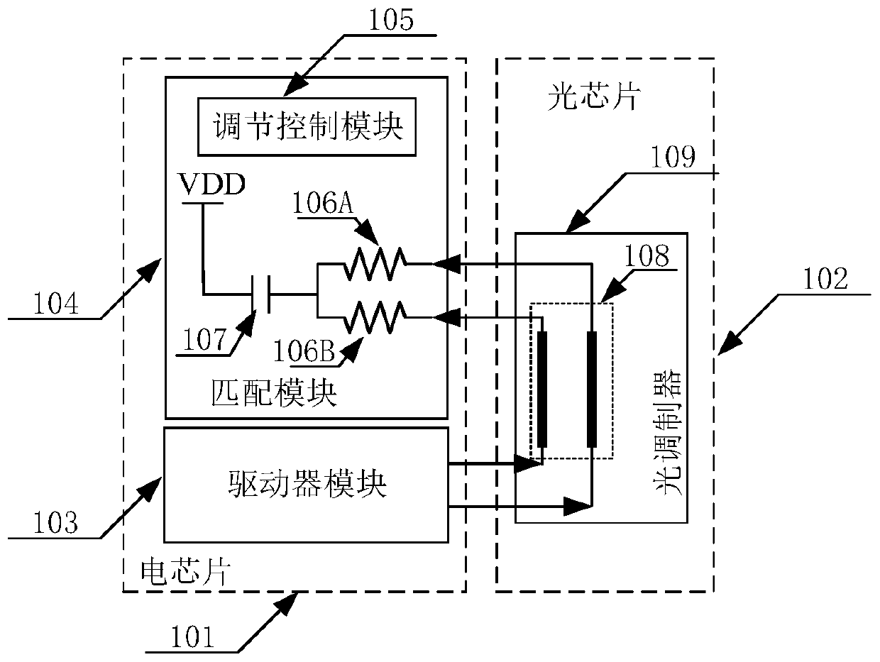
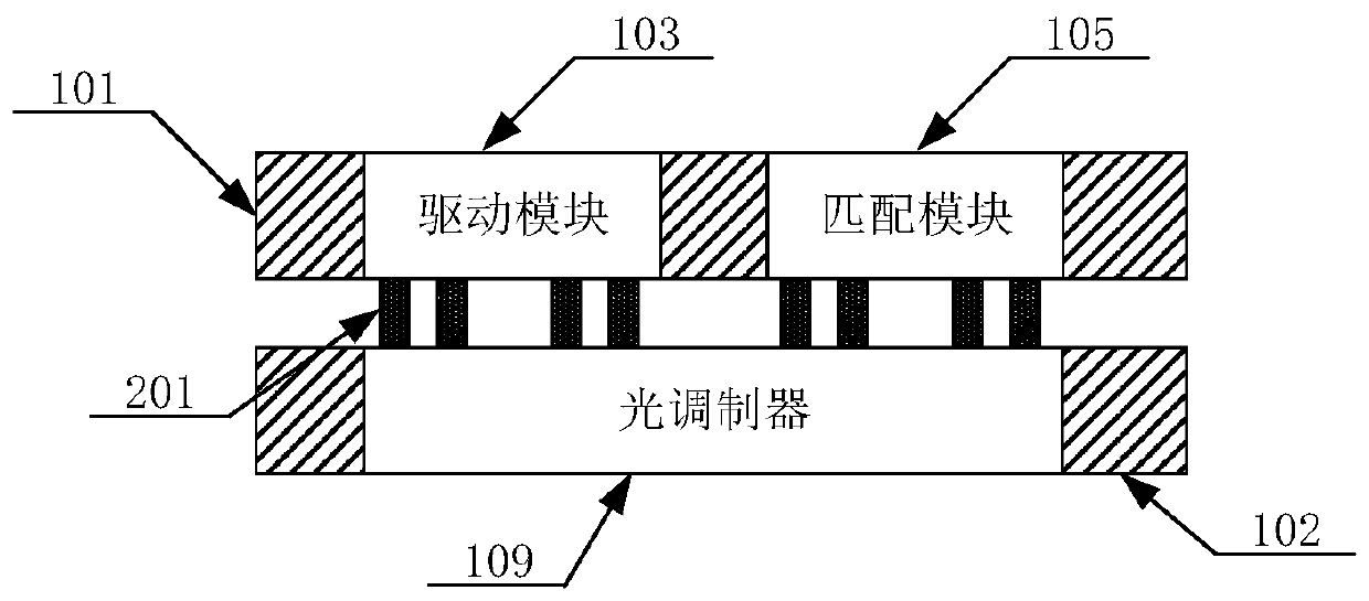
The invention discloses an optical transmitter, which is applied to a photoelectric interconnection interface system and comprises an electric chip and an optical chip which are connected with each other. The electric chip comprises a driver module and a matching module. The driver module is used for generating a driving signal and transmitting the driving signal to the optical chip. The optical chip is used for modulating the optical signal according to the driving signal to obtain a modulation signal and outputting the modulation signal. The matching module is used for performing impedance matching on the driving signal output by the optical chip. The optical transmitter has the advantages that the device selection of the optical transmitter is not limited, and the impedance matching precision is high.

Description

technical field [0001] The invention relates to the technical field of photoelectric communication, in particular to an optical transmitter. Background technique [0002] Impedance matching is a part of microwave electronics. It is mainly used on transmission lines to achieve the purpose that all high-frequency microwave signals can be transmitted to the load point, and no signal will be reflected back to the source point, thereby improving energy efficiency. . [0003] In the design of the existing optoelectronic interconnection interface system, due to the continuous increase of the signal transmission rate, the impedance matching between the electric driver module and the optical module will directly affect the transmission effect and signal quality of high-speed signals. Therefore, in the design process of the electric driver module, it is often considered to design an impedance matching device (circuit) consistent with the characteristic impedance of the optical module...

Claims


Application Information

Patent Timeline
Patent Type & Authority Applications(China)
IPC IPC(8): H04B10/50H04B10/516
CPCH04B10/50H04B10/516
Inventor 纪鹏飞宗诚何卫锋林文淼刘永超毛志刚
Owner SHANGHAI JIAO TONG UNIV
Why Eureka
Try Eureka