
Screen device

A screen and casing technology, applied in the field of screen devices, can solve problems such as poor applicability, time wasting, and increased production costs, and achieve the effect of improving the applicability of splicing

Inactive Publication Date: 2019-10-11
MITAC COMP (SHUN DE) LTD +1
View PDF12 Cites 0 Cited by
  • Summary
  • Abstract
  • Description
  • Claims
  • Application Information

AI Technical Summary

Problems solved by technology

The common splicing method is to install multiple fixing strips on the casing of the small-sized screen for locking and combining to form a one-piece large-sized screen. Therefore, the casing of the small-sized screen needs to reserve screw holes for fixing The bar lock is set on the shell, so most of them first design the pattern that needs to be spliced ​​into a large-size screen and reserve screw holes on the shell and produce the style of the fixing bar. Usually, only one splicing method is applicable. The applicability is not good. If you want to splice it into another large-size screen, you need to re-open the corresponding screw holes and produce the fixed strips of the required style. It is a waste of time and increases the production cost. Further research is urgently needed. improve

Method used


Image

  • Screen device
  • Screen device
  • Screen device

Examples


Embodiment Construction

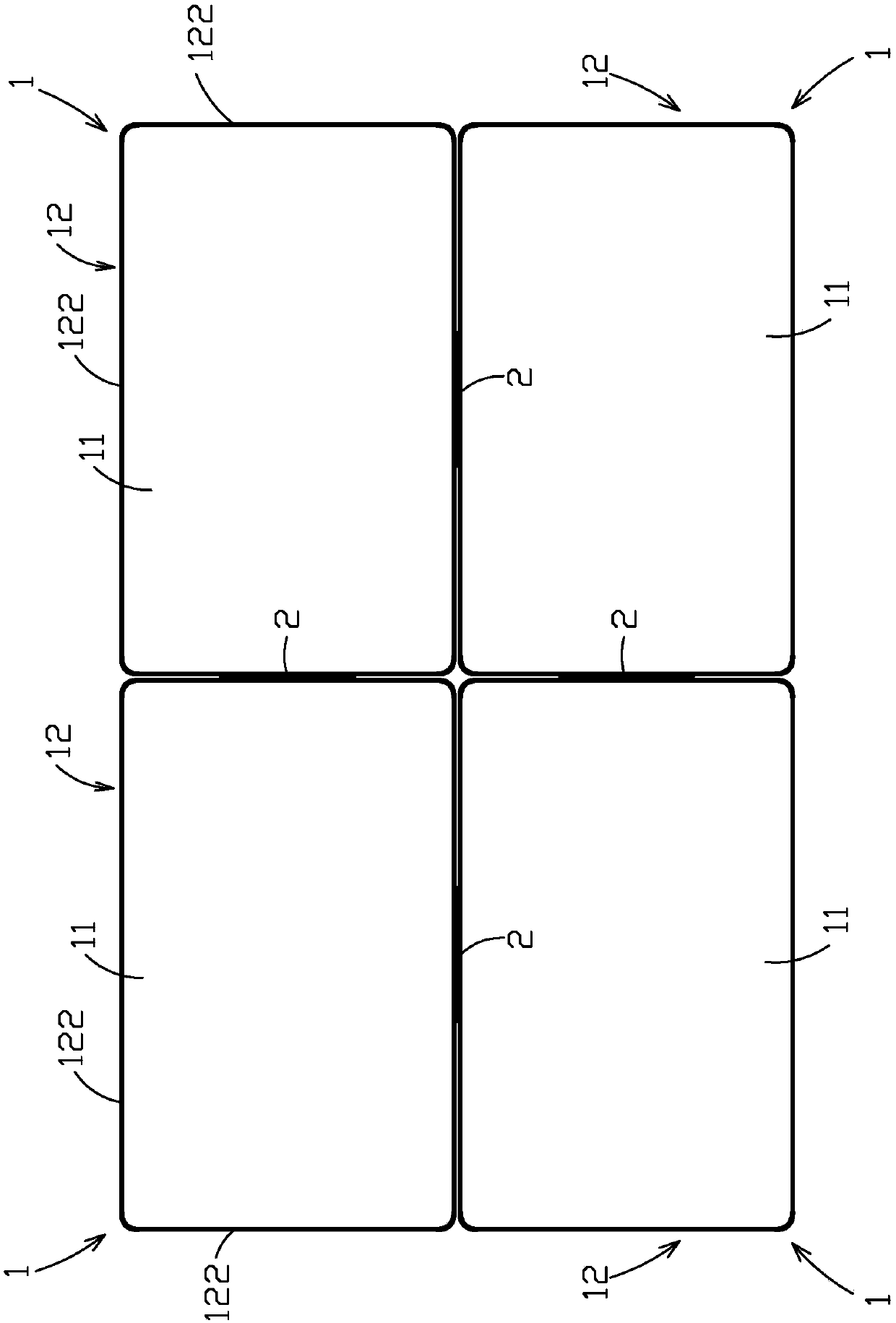
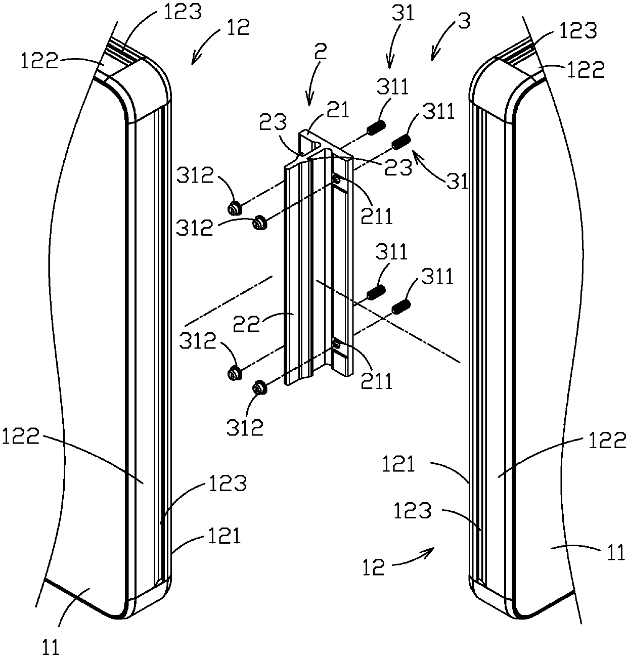
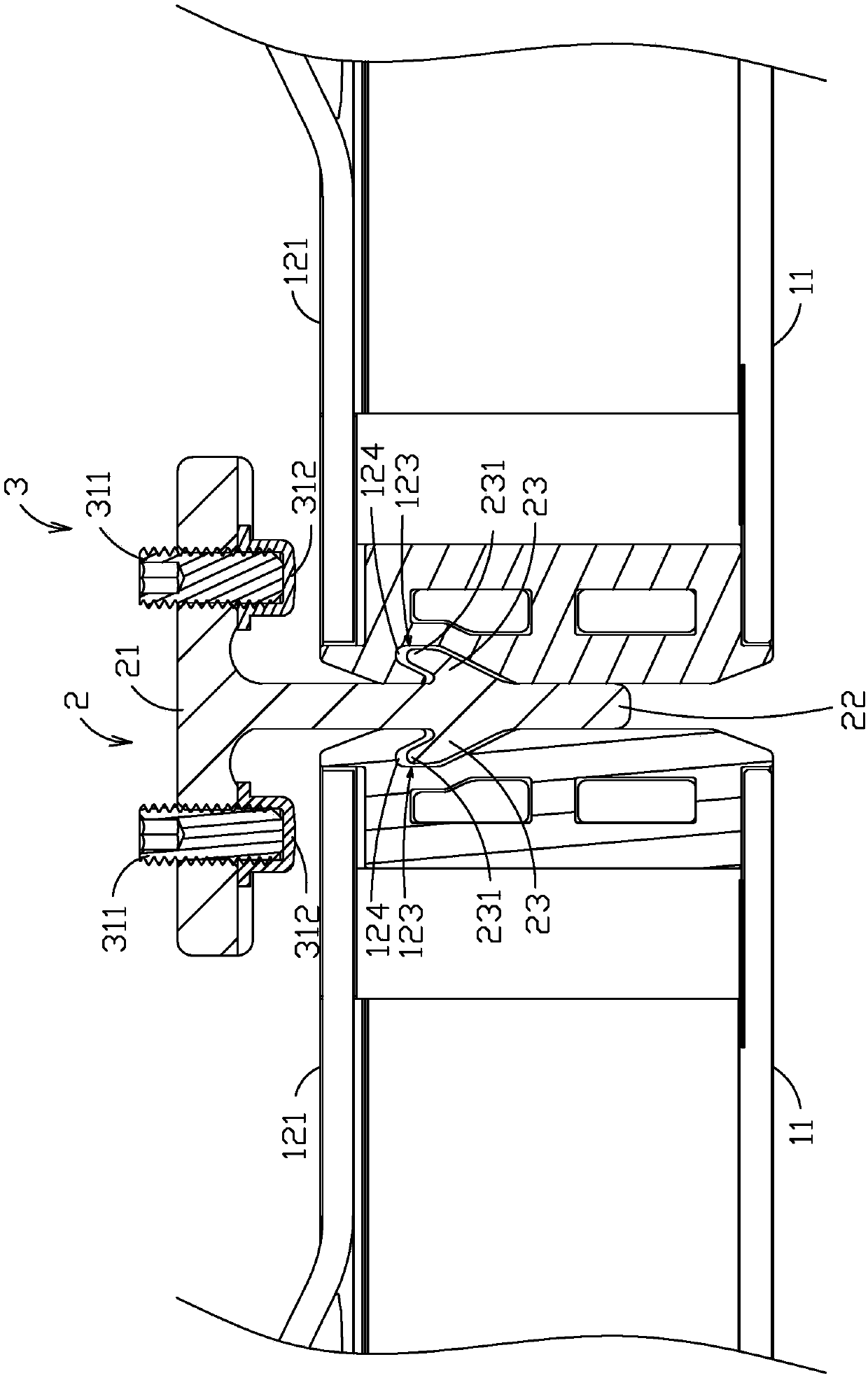
[0015] see figure 1 , figure 2 , image 3 and Figure 4 As shown, the present invention provides an embodiment of a screen device, which includes a plurality of display units 1 , a plurality of fixing brackets 2 , and a fixing unit 3 .

[0016] Each display unit 1 includes a screen 11 and a casing 12 surrounding the screen 11 . Each housing 12 has a body 121 (not shown), a plurality of frame 122 extending from the body 121 to the direction of the corresponding screen 11 and surrounding the screen 11, and a plurality of positioning slides recessed in the frame 122 Slot 123.

[0017] Each fixing bracket 2 can be combined with the shells 12 of two adjacent display units 1, and includes a fixed wall 21, a direction extending from the fixed wall 21 to the direction away from the fixed wall 21 and located in two adjacent shells 12 There is a partition wall 22 between them, and two engaging walls 23 located on two opposite sides of the partition wall 22 and extending from the p...


PUM


Abstract

The invention provides a screen device. The screen device comprises a plurality of display units, a plurality of fixing brackets and a fixing unit, wherein each display unit comprises a screen and a shell; each shell is provided with a plurality of frames and a plurality of locating sliding chutes; each fixing bracket can combine the shells of the adjacent display units, and comprises a fixing wall and two clamping and embedding walls; each clamping and embedding wall can be embedded in the adjacent locating sliding chutes; the fixing unit comprises a plurality of fixing parts penetrating through the fixing walls; each fixing part is provided with a rod penetrating through the corresponding fixing wall, and a butting part movably butting to the corresponding shell; and due to the design that the clamping and embedding walls of each fixing bracket are embedded in the adjacent locating sliding chutes for combining the adjacent display units, and the butting parts press and push the shells of the display units, and each fixing bracket is in the clamping fixing state, the clamping and embedding walls are limited in the corresponding locating sliding chutes and can not be drawn towardsthe direction far away from the locating sliding chutes, and therefore, the splicing application is effectively promoted.

Description

technical field [0001] The present invention relates to a screen device, in particular to a screen device with good applicability and easy assembly and splicing. Background technique [0002] Nowadays, the application of large-size screen devices such as TV walls and large-scale electronic advertising billboards can be seen everywhere. Generally speaking, large-size screen devices are presented by splicing and assembling multiple small-size screens. The common splicing method is to install multiple fixing strips on the casing of the small-sized screen for locking and combining to form a one-piece large-sized screen. Therefore, the casing of the small-sized screen needs to reserve screw holes for fixing The bar lock is set on the shell, so most of them first design the pattern that needs to be spliced ​​into a large-size screen and reserve screw holes on the shell and produce the style of the fixing bar. Usually, only one splicing method is applicable. The applicability is n...

Claims


Application Information

Patent Timeline
IPC IPC(8): G09F9/302F16B5/00
CPCF16B5/0036G09F9/3026
Inventor 陈政宏
Owner MITAC COMP (SHUN DE) LTD
Learn More