Rapid fixing device and method for constructional engineering formwork

A technology of construction engineering and fixing devices, which is applied in the direction of construction, building structure, and on-site preparation of building components. It can solve the problems of long time-consuming vertical formwork, time-consuming and labor-intensive manual movement, and low construction efficiency. Compact design, increased sealing and engaging performance, and solved the effect of inconvenient adjustment

Pending Publication Date: 2022-04-29
CHINA SHANXI SIJIAN GRP
View PDF0 Cites 0 Cited by
  • Summary
  • Abstract
  • Description
  • Claims
  • Application Information

AI Technical Summary

Problems solved by technology

However, there are the following disadvantages: 1. The vertical formwork is heavy, and manual movement is time-consuming and laborious and cannot be precisely controlled; 2. It takes a long time to adjust the vertical formwork, wastes a lot of labor, and the construction efficiency is low

Method used


Image

  • Rapid fixing device and method for constructional engineering formwork
  • Rapid fixing device and method for constructional engineering formwork
  • Rapid fixing device and method for constructional engineering formwork

Examples


Embodiment 1

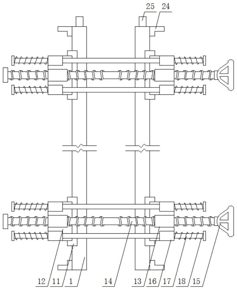
[0032] Embodiment 1: This embodiment provides a fast fixing device for construction engineering formwork, see figure 1 , figure 2 , image 3 Specifically, it includes a pair of templates 1, an adjustment mechanism, and hinges. A pair of templates 1 are placed vertically and parallel on the ground, and the four corners of the outer surface of each template 1 are provided with inlaid and welded U-shaped plates 11 , the outer surface of each U-shaped plate 11 is provided with an L-shaped plate 12, see Figure 5 , Image 6 , the two adjacent L-shaped plates 12 are connected by an adjustment mechanism; the middle part of the outer side of each template 1 is provided with a square plate 2, and each square plate 2 is connected to the corresponding L-shaped plate 12 through a hinge connect.

[0033] Specifically, the adjustment mechanism includes a threaded cylinder 13 and a two-way lead screw 14. The middle part of the side of each L-shaped plate 12 is provided with a horizontal...

Embodiment 2

[0036] Embodiment 2: In Embodiment 1, there is still the problem that the L-shaped plate is not firmly fixed. Therefore, on the basis of Embodiment 1, this embodiment also includes a hinge:

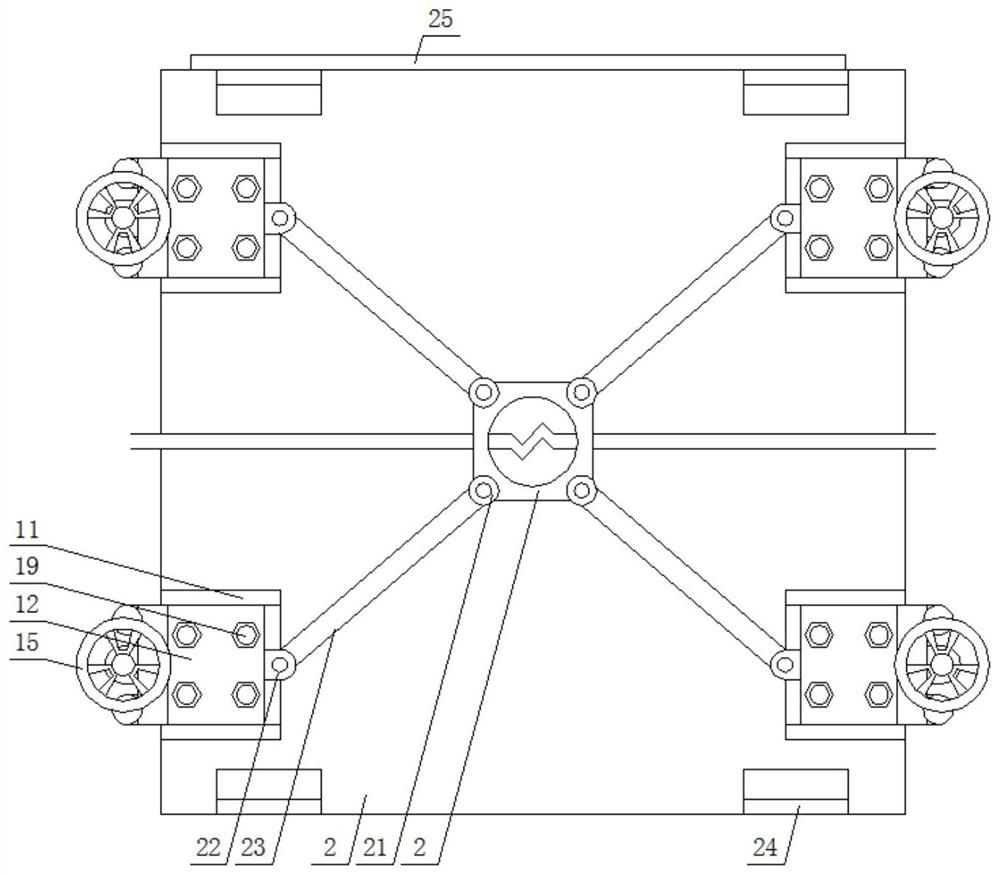
[0037] Specifically, the hinge includes a hinge rod 23, the middle of the square plate 2 is provided with a circular hole, the four corners of the square plate 2 are provided with a first hinge seat 21, and the inner side of each L-shaped plate 12 is provided with a circular hole. There is a second hinged seat 22, and the two ends of the hinged rod 23 are respectively hinged with the corresponding first hinged seat 21 and the second hinged seat 22; The hinged seat 21 and the second hinged seat 22 are movable latches, so that an effective fixed connection is added between the L-shaped plates 1 at the four corners of the template 1 .

Embodiment 3

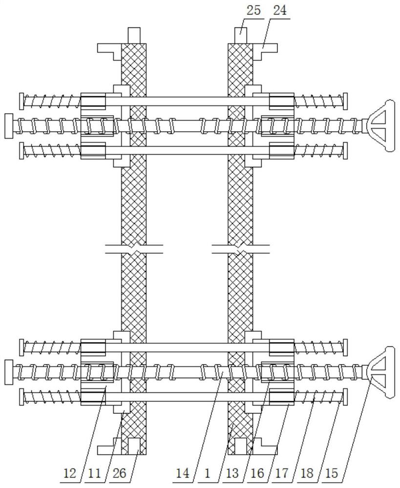
[0038] Embodiment 3: In embodiment 1, there is also the problem of inconvenient splicing of multiple sets of templates. Therefore, on the basis of embodiment 1, see Figure 4 In this embodiment, a rectangular groove 26 is provided on the bottom surface of the formwork 1, and a rectangular clamping plate 25 is provided on the top surface of the formwork 1, and the rectangular clamping plate 25 is engaged in the rectangular groove 26 of another set of formwork 1, thereby increasing the formwork 1 and The sealing engagement performance when another set of formwork 1 is in contact.

[0039] In the present invention, a pair of L-shaped foot plates 24 are provided on the top and bottom sides of the outer surface of the formwork 1, and each L-shaped foot plate 24 is connected with the L-shaped foot plate 24 of another set of formwork 1 through connecting bolts. The cooperating use of the foot plate 24 facilitates the splicing and assembly of multiple sets of templates 1 .


PUM


Abstract

The invention relates to the technical field of constructional engineering, and discloses a constructional engineering formwork rapid fixing device which comprises a pair of formworks, adjusting mechanisms and hinge pieces, U-shaped plates are arranged at the four corners of the outer side face of each formwork, L-shaped plates are arranged on the outer side face of each U-shaped plate, and every two adjacent L-shaped plates are connected through the corresponding adjusting mechanism; a square plate is arranged in the middle of the outer side face of each formwork, and each square plate is connected with the corresponding L-shaped plate through a hinge piece. Through cooperative use of all the mechanisms, the problem that a vertical formwork is inconvenient to adjust is solved, the overall structural design is compact, and on the premise that safety is guaranteed, adjustment of the vertical formwork is completed in a time-saving and labor-saving mode, so that erecting and fixing of the formwork are rapidly completed.

Description

technical field [0001] The invention relates to the technical field of construction engineering, in particular to a fast fixing device for a construction engineering formwork and a fixing method thereof. Background technique [0002] In the construction of construction projects, formwork is widely used as the main material, and wooden formwork is used as the support system. During construction, the workers first bind the steel bars of the wall columns, and then set up the support system. Then the panels and square nails are used to form the formwork. Lift it to the corresponding position by tower crane and fix it. [0003] When hoisting, it is necessary to cooperate with the tower crane manually. After hoisting to the corresponding position, if there is a deviation, the vertical formwork needs to be manually moved. However, there are the following disadvantages: 1. The vertical formwork is heavy, and manual movement is time-consuming and laborious and cannot be accurately c...

Claims


Application Information

Patent Timeline
IPC IPC(8): E04G17/00E04G17/065
CPCE04G17/001E04G17/0655
Inventor 韩瑛郑永春常春段强文灿锦孟瑾卜琼郑志超
Owner CHINA SHANXI SIJIAN GRP
Why Eureka
Try Eureka