Camera lens
A lens and lens barrel technology, applied in the field of lenses, can solve the problem of large lens size, and achieve the effect of increasing the screen ratio and improving the aesthetics.
Pending Publication Date: 2019-10-18
ZHEJIANG SUNNY OPTICAL CO LTD
View PDF0 Cites 0 Cited by
- Summary
- Abstract
- Description
- Claims
- Application Information
AI Technical Summary
Problems solved by technology
[0005] The main purpose of the present application is to provide a lens to solve the problem of larger lens size in the prior art
Method used
View moreImage
Smart ImageViewing Examples
Examples
Embodiment
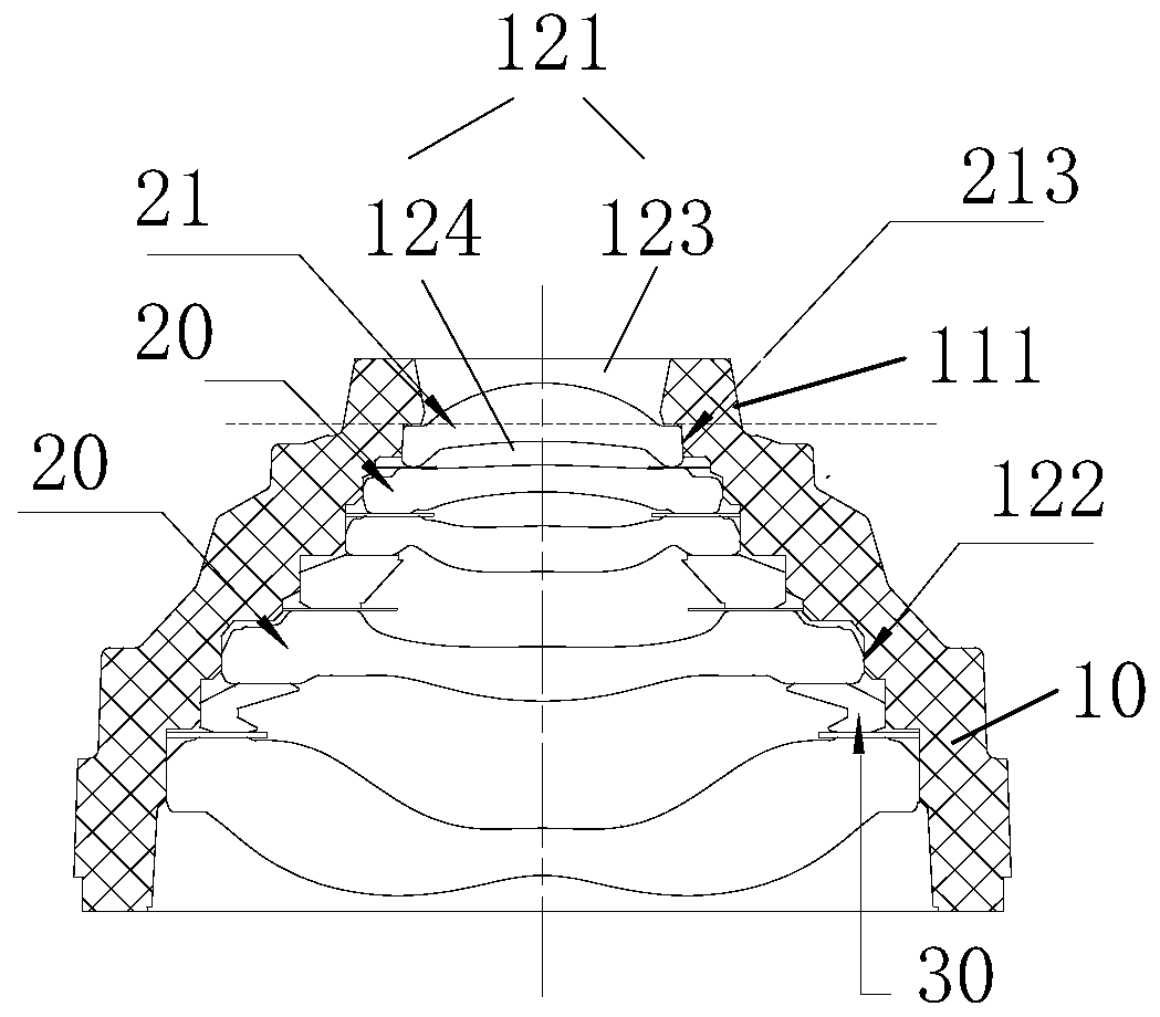
[0069] The structure of the lens is as figure 1 and Figure 8 As shown, the lens includes a lens barrel 10 and a lens 20, and its specific structure can refer to the above description and Figure 2 to Figure 7 As shown, it will not be repeated here.
Login to View More PUM
 Abstract
The application provides a camera lens. The camera lens comprises a camera lens tube which comprises a camera lens tube body and a holding cavity located in the camera lens tube body, wherein the camera lens tube body comprises an outer end and an inner end and the holding cavity comprises a first holding cavity and a second holding cavity on an axial direction of the camera lens tube, and the first holding cavity is closer to the outer end of the camera lens tube body in comparison with the second holding cavity on the axial direction of the camera lens tube; and multiple lenses, wherein at least one of the multiple lenses comprises a trimmed lens, and at least one trimmed lens is located in the first holding cavity. In the camera lens, the trimmed lens is arranged in the first holding cavity close to the outer end, the size of the trimmed lens is smaller in comparison with the size of the conventional lens; under the same optical design, 10-25% of outer end lens caliber of the cameralens can be reduced, when the camera lens is applied to the mobile and like electronic equipment, the size occupied by the camera lens in the screen of the mobile phone and like electronic equipmentcan be reduced, thereby increasing the screen-to-body ratio of the screen of the mobile phone and like electronic equipment.
Description
technical field [0001] The present application relates to the lens field, in particular, to a lens. Background technique [0002] In the context of the rise of full-screen mobile phones, first there is a relatively large notch screen, then a smaller water drop screen, and then a hole-digging screen with only a small circle inside the screen. This is a process of gradually approaching the ultimate full screen. . These components on the front have become a stumbling block in front of the full screen. Manufacturers choose to achieve a full screen by compressing the installation space of the top components. Therefore, reducing the size of the imaging lens becomes particularly important. [0003] The main structures of existing mobile phone lenses on the market include a lens barrel and a lens group installed in the lens. The lens is a disc-shaped rotating structure, and the corresponding inner wall of the lens barrel is a circular through-hole structure. Such a large structure...
Claims
Login to View More Application Information
Patent Timeline
 IPC IPC(8): G02B7/02G03B30/00
CPCG02B7/021
Inventor 丁先翠白洪涛朱佳栋戴付建赵烈烽
Owner ZHEJIANG SUNNY OPTICAL CO LTD
Features
- R&D
- Intellectual Property
- Life Sciences
- Materials
- Tech Scout
- Unparalleled Data Quality
- Higher Quality Content
- 60% Fewer Hallucinations
Learn More Browse by: Latest US Patents, China's latest patents, Technical Efficacy Thesaurus, Application Domain, Technology Topic, Popular Technical Reports.
© 2025 PatSnap. All rights reserved.Legal|Privacy policy|Modern Slavery Act Transparency Statement|Sitemap|About US| Contact US: help@patsnap.com


