Eureka AIR delivers breakthrough ideas for toughest innovation challenges, trusted by R&D personnel around the world.

Digital background correction method based on least mean square algorithm

A calibration method and digital technology, applied in the direction of analog/digital conversion calibration/test, analog/digital conversion, signal transmission system, etc., can solve the problems of invalid correction, no highest-order capacitance correction, and inability to correct the mismatch direction, etc. achieve the effect of ensuring correctness

Active Publication Date: 2019-10-18
UNIV OF ELECTRONICS SCI & TECH OF CHINA +1
View PDF4 Cites 13 Cited by
  • Summary
  • Abstract
  • Description
  • Claims
  • Application Information

AI Technical Summary

Problems solved by technology

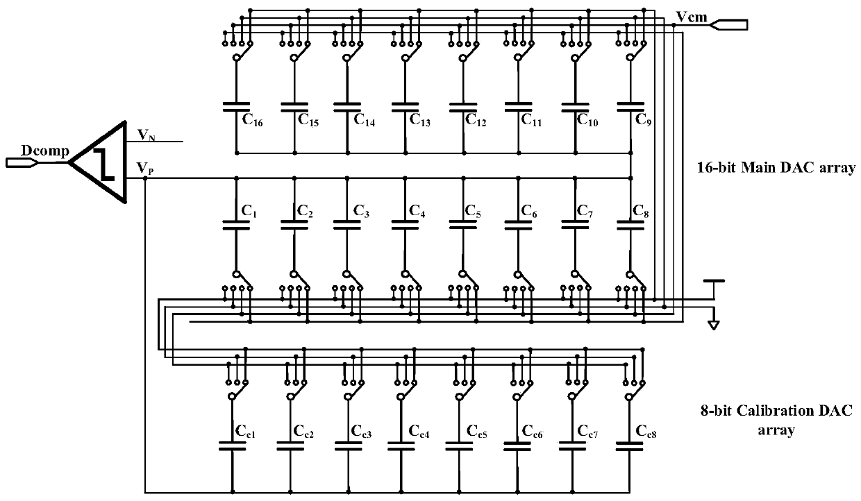
[0025] Aiming at the deficiencies that the above-mentioned traditional digital background correction method based on the split type split ADC cannot be corrected when the mismatch direction is consistent and the highest bit capacitance correction is not performed, the present invention proposes a digital method based on the least mean square algorithm (LMS algorithm). The background calibration method uses a non-binary capacitor array, which can effectively solve the problem of invalid calibration caused by the mismatching direction of the two ADC capacitors; at the same time, the non-binary capacitor array introduces redundancy to ensure the feasibility of digital calibration; finally, The capacitor with the highest weight is specially designed so that it can be effectively corrected

Method used


Image

  • Digital background correction method based on least mean square algorithm
  • Digital background correction method based on least mean square algorithm
  • Digital background correction method based on least mean square algorithm

Examples


Embodiment Construction

[0051] Below in conjunction with accompanying drawing, further illustrate the present invention through embodiment.

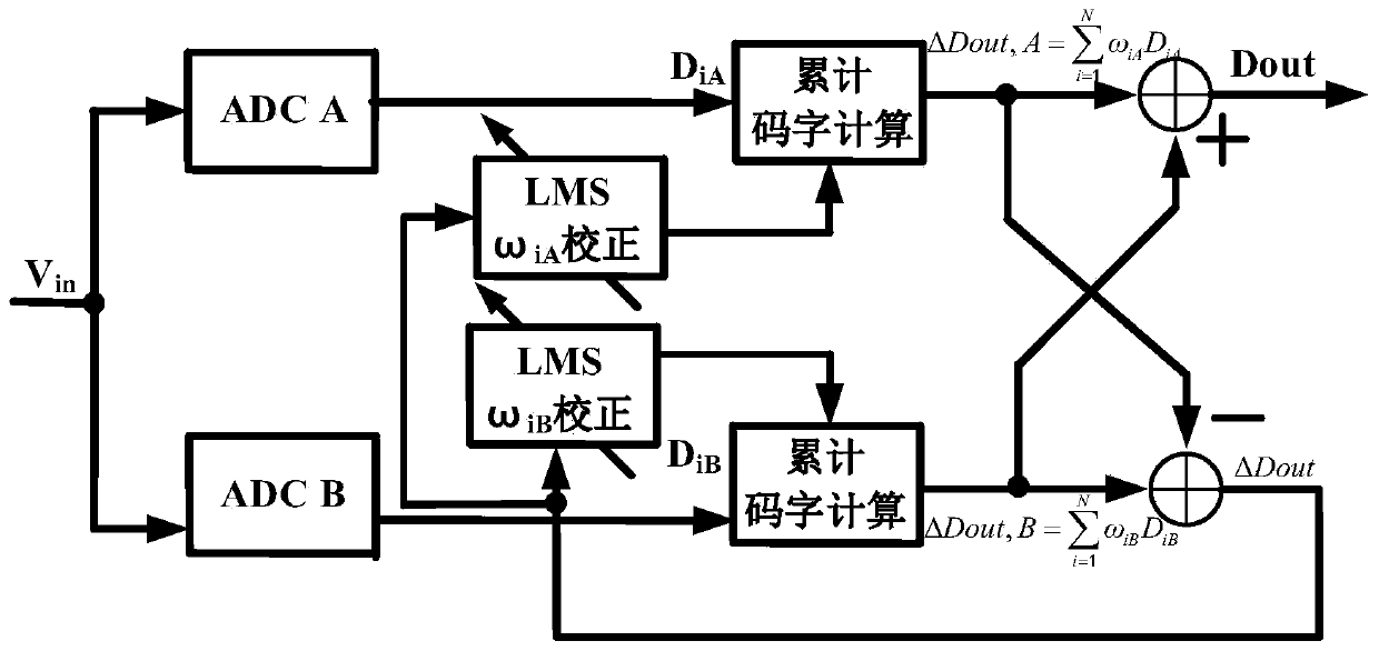
[0052] Such as figure 1 Shown is a frame diagram of a digital background correction method based on the least mean square algorithm proposed by the present invention, and the structure that adopts the method of the present invention to correct includes split SAR ADC, LMSω iA Calibration module, LMSω iB Correction module, the first cumulative codeword calculation module and the second cumulative codeword calculation module, the split SAR ADC includes the first analog-to-digital conversion module ADC A and the second analog-to-digital conversion module ADC B, the first analog-to-digital conversion module ADC A Connect the input signal V with the input terminal of the second analog-to-digital conversion module ADC B module in , the output end of the first analog-to-digital conversion module ADC A module is connected to the first input end of the first accumulate...


PUM


Abstract

The invention discloses a digital background correction method based on a least mean square algorithm, which is suitable for a split SAR ADC. The method comprises the following steps: firstly, settinga split SAR ADC, and performing digital background correction based on a minimum mean square algorithm on the set split SAR ADC, wherein the split type SAR ADC comprises two ADC modules, a main DAC capacitor array in each ADC module adopts a non-binary capacitor array; meanwhile, the weight of the highest-order capacitor in the main DAC redundant capacitor array is set to be minimum, so that eachcapacitor including the capacitor with the maximum weight in the main DAC capacitor array can be effectively corrected through random switching of the correction DAC capacitor array, and the linearity and the dynamic range of the ADC are improved; the introduction of the correction DAC random switching mode can effectively solve the problem that the correction is invalid due to the fact that thetwo ADC capacitors are not consistent in direction. In addition, redundancy is introduced into the main DAC capacitor array, so that dynamic errors introduced into the quantization process of the system can be weakened, the correctness of each switching is ensured, and the iteration speed is increased.

Description

technical field [0001] The invention belongs to the technical field of analog integrated circuits, and in particular relates to a digital background correction method based on a least mean square algorithm (LMS), which is used for correcting a capacitance array of a high-precision successive approximation analog-to-digital converter (SAR ADC). Background technique [0002] With the improvement of the precision of the analog-to-digital converter (ADC), the matching precision of the capacitor determines the static and dynamic performance of the ADC in a small-scale process. In addition to a better layout of the capacitor array layout, we also need to correct the capacitor array. The current mainstream correction methods include digital correction and analog correction. Digital correction means that the elimination of capacitor mismatch is completed in the digital domain. The weight of each capacitor corresponds to a digital codeword. This codeword corresponds to the digital w...

Claims


Application Information

Patent Timeline
Patent Type & Authority Applications(China)
IPC IPC(8): H03M1/10H03M1/46
CPCH03M1/1004H03M1/468
Inventor 于奇王艾意田明张中余先银李靖宁宁
Owner UNIV OF ELECTRONICS SCI & TECH OF CHINA
Why Eureka
Eureka Blog
Learn More