
Charging control method, charging device, storage medium and electronic equipment

A charging control method and technology of a charging device are applied in the fields of storage media and electronic equipment, charging control method and charging device, and can solve the problems of reducing charging efficiency, easily falling into the same unit, affecting the charging efficiency of a platform, etc., so as to ensure the charging efficiency. , the effect of reducing the probability of charging interruption

Inactive Publication Date: 2019-10-22
杨绍
View PDF7 Cites 9 Cited by
  • Summary
  • Abstract
  • Description
  • Claims
  • Application Information

AI Technical Summary

Problems solved by technology

In order to improve the charging efficiency of the charging platform and expand the contact range, the patent discloses the use of multiple pairs of conductive feet to contact the platform, but in the actual charging process, one unit is still used to charge one conductive foot.
This method of operation has the following problems: when the same conductive foot contacts multiple units at the same time, due to the choice of platform and actual uncontrollable factors, the charging efficiency will be reduced, specifically: for example, when the conductive foot contacts two units at the same time When A and B, since the conductive leg has a certain cross-sectional area, when the conductive leg has 70% of the cross-sectional area contacting unit A and 20% of the cross-sectional area contacting unit B (there is also 10% of the gap between units A and B ), at this time, the platform can use either unit A or unit B to charge the device, but no matter whether unit A or unit B is used, due to the limitation of the cross-sectional area of ​​the contact between the conductive legs and the unit, the charging current is lower than that of the ideal charging current. The current drops, thus affecting the charging efficiency of the platform
Finally, there are uncontrollable factors such as poor contact in practical applications. These factors will complicate the charging situation. Simply providing a unit corresponding to a conductive foot to charge the device cannot cope with these complicated situations.
[0005] In addition, this method of charging with one unit corresponding to one conductive foot also has the following problems: when there is a displacement between the device and the platform during the charging process (caused by wind or other factors), it is easy to cause The conductive feet are disconnected from the unit being activated. At this time, the platform needs to re-scan to identify new units that are in contact with the conductive feet before continuing to restore the charging state, which reduces the charging efficiency.
In order to solve this problem, the area of ​​a single unit can be enlarged to make it much larger than the contact area of ​​the conductive feet, but this setting method cannot be applied to cars or aircraft of different sizes, because the two parts of the car or aircraft The conductive feet must be in contact with different units, so that the positive and negative electrodes can be guaranteed. If the area of ​​a single unit is too large, the two conductive feet of a car or aircraft can easily fall into the same unit, and charging cannot be realized.
Another way to solve this problem is to reduce the cross-sectional area of ​​the conductive legs so that it is much smaller than the area of ​​a single unit, but in this way, since the contact area between the conductive legs and the unit is reduced, the charging current will be directly reduced, that is, the charging current will be reduced. charging efficiency

Method used

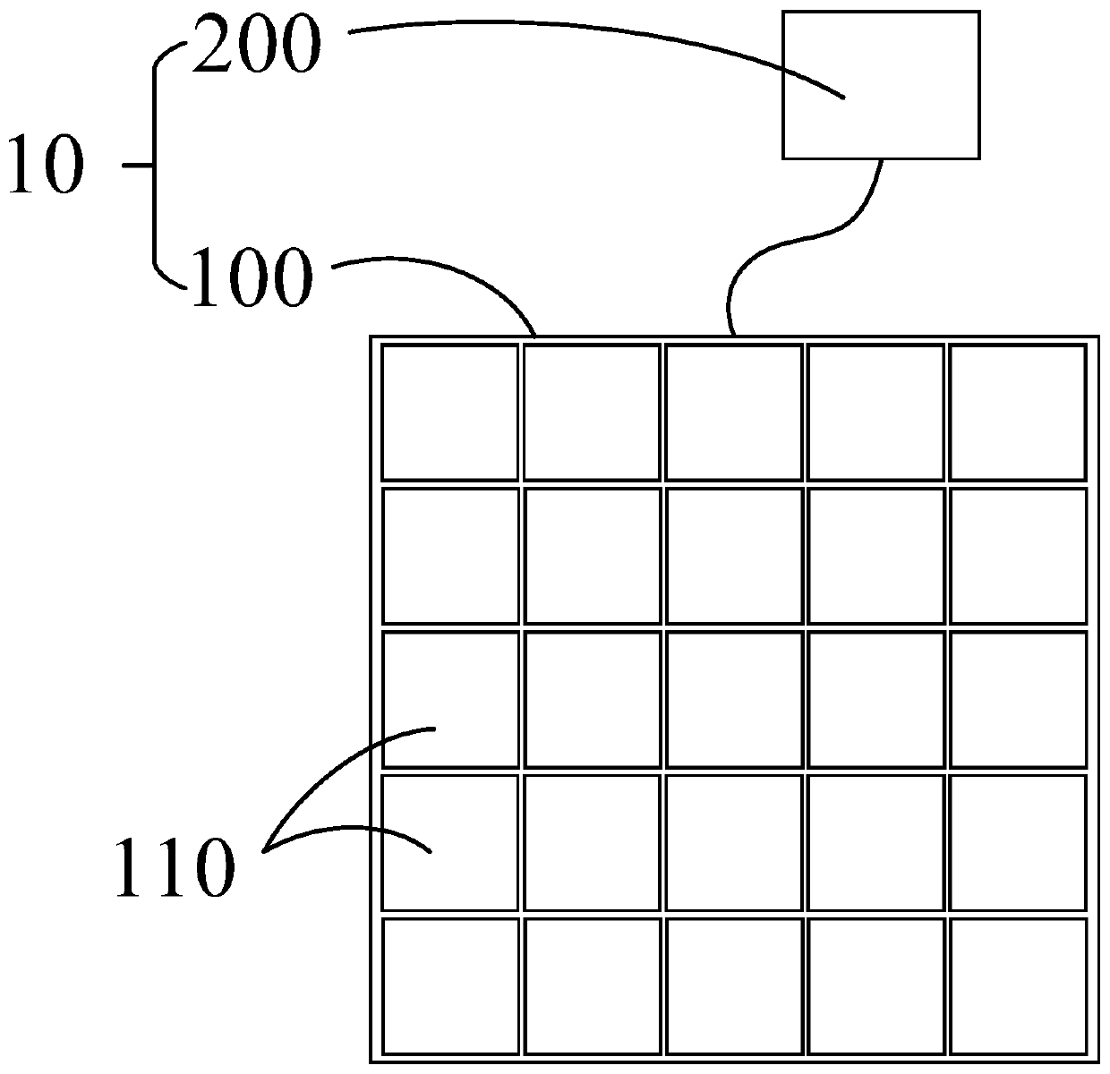
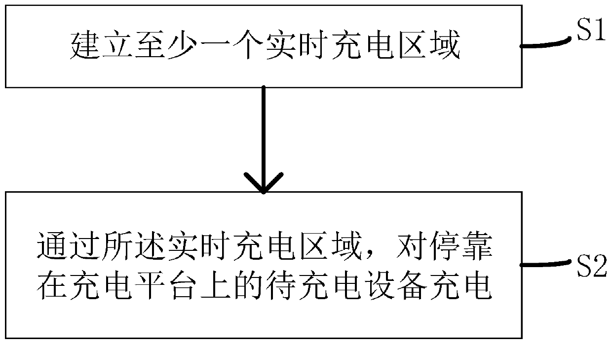
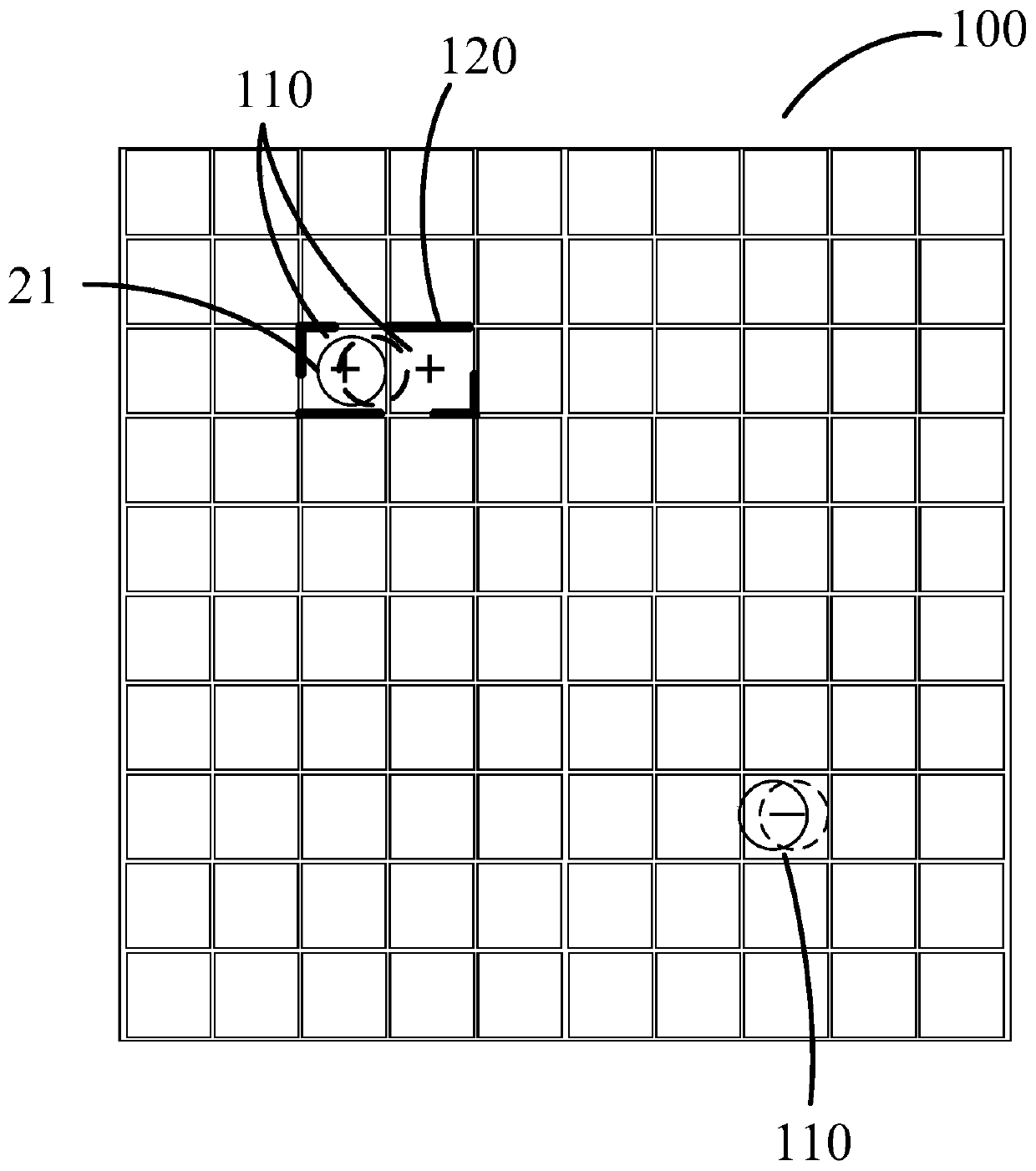

Image

  • Charging control method, charging device, storage medium and electronic equipment
  • Charging control method, charging device, storage medium and electronic equipment
  • Charging control method, charging device, storage medium and electronic equipment

Examples


Embodiment Construction

[0036] Embodiments of the present invention are described in detail below, examples of which are shown in the drawings, wherein the same or similar reference numerals denote the same or similar elements or elements having the same or similar functions throughout. The embodiments described below by referring to the figures are exemplary only for explaining the present invention and should not be construed as limiting the present invention.

[0037] In describing the present invention, it should be understood that the terms "center", "longitudinal", "transverse", "length", "width", "thickness", "upper", "lower", "front", " Orientation indicated by rear, left, right, vertical, horizontal, top, bottom, inside, outside, clockwise, counterclockwise, etc. The positional relationship is based on the orientation or positional relationship shown in the drawings, which is only for the convenience of describing the present invention and simplifying the description, rather than indicating ...


PUM


Abstract

The invention provides a charging control method which is used for a charging device provided with a charging platform. The charging platform is formed by arranging a plurality of conductive units. The charging control method comprises the following steps: establishing at least one real-time charging area, wherein the real-time charging area comprises at least two adjacent conductive units; charging a to-be-charged device parked on the charging platform through the real-time charging area; and controlling the output voltage of each conductive unit in the real-time charging area, so that the output voltage of each conductive unit in the real-time charging area is kept to be the same or synchronously changed in the charging process of the to-be-charged device. The invention also provides a charging device, a storage medium and electronic equipment, so as to provide a more stable and efficient charging effect.

Description

technical field [0001] The invention relates to the technical field of electronic software, in particular to a charging control method, a charging device, a storage medium and electronic equipment. Background technique [0002] Traditional charging methods generally include contact charging and wireless charging. Contact charging generally requires contact between a socket and a plug to achieve charging, while wireless charging generally transfers energy through an electromagnetic field. [0003] US Patent US20160336772A1 discloses a charging device, in which a plurality of individually arranged units are arranged to form a chargeable platform, and the voltage of each individually arranged unit can be controlled by a controller. The charging platform can charge the unmanned car or aircraft, specifically: the unmanned car or aircraft is parked on the charging platform, and the internal battery of the unmanned car or aircraft is connected to the unit of the charging platform t...

Claims


Application Information

Patent Timeline
Patent Type & Authority Applications(China)
IPC IPC(8): H02J7/00
CPCH02J7/0027
Inventor 杨绍
Owner 杨绍
Learn More