Adaptive Magnetic Wireless Charger

a wireless charger and adapter technology, applied in the direction of magnets, magnetic bodies, transportation and packaging, etc., can solve the problems affecting charging efficiency, achieve the effect of reducing interference of magnets with wireless charging magnetic waves, ensuring wireless charging efficiency, and simple overall structur

Inactive Publication Date: 2021-06-03
SHEN ZHEN SHI AIKER ELECTRONICS TECH CO LTD
View PDF0 Cites 7 Cited by
  • Summary
  • Abstract
  • Description
  • Claims
  • Application Information

AI Technical Summary

Benefits of technology

[0009]By adoption of the above solution, the holding plate is disposed in the accommodating cavity to install the magnet, and the spring is arranged to provide an ejection force, so that when not attracted, the magnet will be retained at the bottom of the accommodating cavity to satisfy the charging requirement of conventional wirelessly rechargeable mobile phones, the interference of the magnet on wireless charging magnetic waves is reduced, and the wireless charging efficiency is guaranteed; when a mobile phone supporting the magnetic wireless function is placed on the adaptive magnetic wireless charger, a magnetic ring in the mobile phone will attract the magnet in the charging dock, the spring is compressed, and the holding plate moves upwards to satisfy the magnetic wireless charging requirement of the mobile phone; and the adaptive magnetic wireless charger is simple in overall structure, easy to operate, and good in practicability.

Problems solved by technology

However, when a mobile phone only supporting a wireless charging function, but not supporting a magnetic function is placed on the magnetic wireless charging dock to be charged, charging can be realized, but it may deviate from the charging dock due to lack of magnetic correction, and a magnetic of the charging dock is close to a wireless coil of the mobile phone, the magnetic field generated by the magnet may interfere with electromagnetic waves generated by the wireless coil, thus affecting the charging efficiency.

Method used


Image

  • Adaptive Magnetic Wireless Charger
  • Adaptive Magnetic Wireless Charger

Examples


Embodiment Construction

[0013]The embodiments of the invention will be explained in detail below in conjunction with the accompanying drawings, but the invention can also be implemented in other different manners defined and included by the claims.

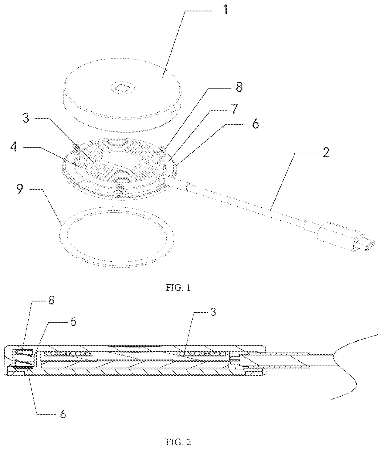
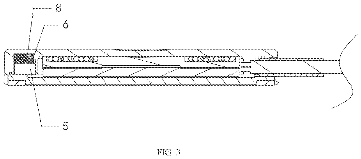
[0014]As shown in FIG. 1 to FIG. 3, this embodiment provides an adaptive magnetic wireless charger, comprising a charging dock 1 and a power line 2, wherein a wireless charging module 3 is arranged in the charging dock 1, an accommodating cavity 5 is defined around the wireless charging module 3 by a partition plate 4, the power line 2 is connected to the wireless charging, module 3, a holding plate 6 is disposed in the accommodating cavity 5, magnets 7 and springs 8 are mounted, on the holding plate 6, and one end of each spring 8 abuts against an inner top surface of the charging dock 1. Wherein, the elastic force of the springs 8 is smaller than the attractive force between the magnets 7 and a magnetic rig of a mobile phone.

[0015]The adaptive magnetic wireless...


PUM


Abstract

An adaptive magnetic wireless charger comprises a charging dock and a power line. A wireless charging module is arranged in the charging dock, an accommodating cavity is defined around the charging dock by a partition plate, the power line is connected to the wireless charging module, a holding plate is disposed in the accommodating cavity, a magnetic and a spring are mounted on the holding plate, and one end of the spring abuts against an inner top surface of the charging dock.

Description

BACKGROUND OF THE INVENTION1. Technical Field[0001]The invention relates to the technical field of wireless chargers, in particular to an adaptive magnetic wireless charger.2. Description of Related Art[0002]With the continuous development of science and technology, wireless chargers, as a new charging technique, have been widely applied to different electronic products, particularly mobile phones. The wireless chargers are ceaselessly innovated to be applied to products more easily.[0003]At present, there are two wireless charging techniques for mobile phones, where one is non-magnetic charging, and the other one is magnetic charging. Magnetic wireless charging docks with a magnetic wireless charging function are typically used for charging mobile phones supporting the magnetic charging function. However, when a mobile phone only supporting a wireless charging function, but not supporting a magnetic function is placed on the magnetic wireless charging dock to be charged, charging c...

Claims


Application Information

Patent Timeline
Patent Type & Authority Applications(United States)
IPC IPC(8): H02J7/02H02J50/10
CPCH02J7/02H01F38/14H02J50/10H01F7/0252H02J50/005
Inventor SU, YAO
Owner SHEN ZHEN SHI AIKER ELECTRONICS TECH CO LTD
Why Eureka
Try Eureka