
Wireless charging system and wireless charging method

A wireless charging and battery technology, applied to battery circuit devices, current collectors, electric vehicles, etc., can solve the problems of wireless charging efficiency reduction, waste of power resources, and reduced wireless charging convenience, so as to ensure charging efficiency and solve inconvenience problem effect

Inactive Publication Date: 2018-04-20
CHINA UNIV OF GEOSCIENCES (WUHAN)
View PDF4 Cites 6 Cited by
  • Summary
  • Abstract
  • Description
  • Claims
  • Application Information

AI Technical Summary

Problems solved by technology

At present, the wireless charging technology adopts open-loop control or manual control, that is, the process is not controlled during charging, and even if it is controlled, the transmitting part is controlled manually, which reduces the convenience of wireless charging.
At the same time, the resistance of the load battery will change during the charging process, or the resistance of the load battery will be different for different charging objects, which will reduce the efficiency of wireless charging and cause a serious waste of power resources.
Especially in wireless charging in a dynamic environment, the position of the load battery and the wireless power supply changes, and it is difficult to guarantee the charging efficiency of the wireless system

Method used


Image

  • Wireless charging system and wireless charging method
  • Wireless charging system and wireless charging method
  • Wireless charging system and wireless charging method

Examples


Embodiment Construction

[0023] In order to make the purpose, technical solution and advantages of the present invention clearer, the embodiments of the present invention will be further described below in conjunction with the accompanying drawings.

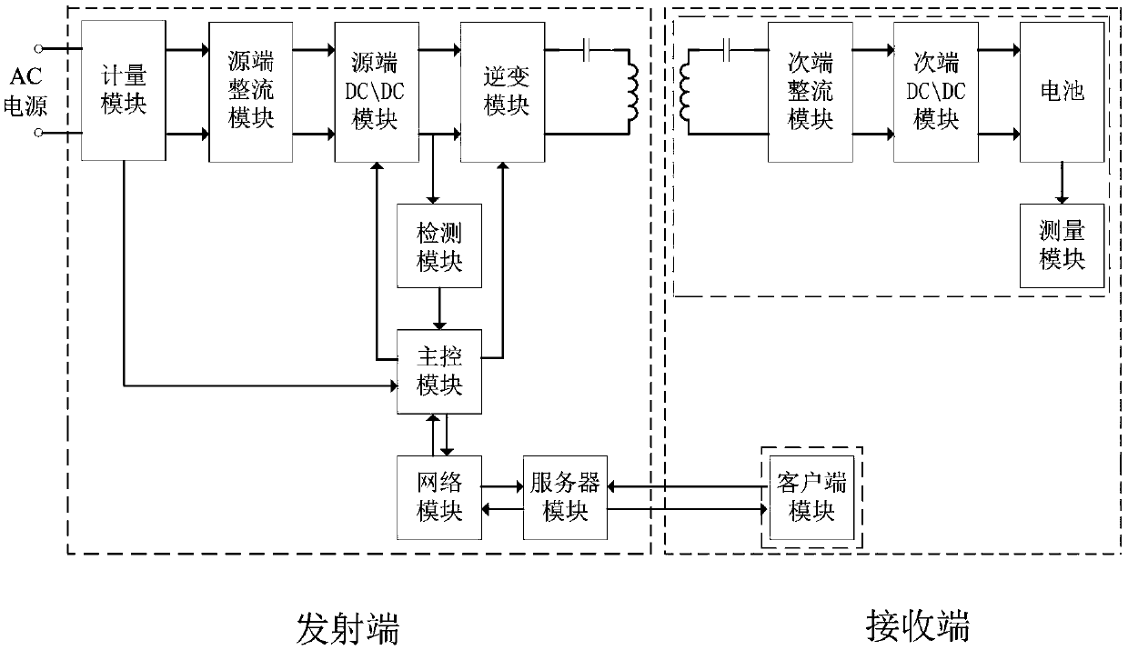
[0024] Please refer to figure 1 , an embodiment of the present invention provides a wireless charging system, including a transmitting end and a receiving end,

[0025] The transmitter includes:

[0026] A metering module, used for metering and inputting the electricity of the system;

[0027] The source-side rectification module is used to receive external AC power and rectify it into DC power. Since the rectified DC power is pulsating, the source-side rectification module is equipped with a low-pass filter for filtering to obtain a stable DC power. In this embodiment, the source-side rectification module passes A parallel capacitor acts as a low-pass filter;

[0028] The source-end DC / DC module is used to adjust the DC voltage rectified by the sourc...


PUM


Abstract

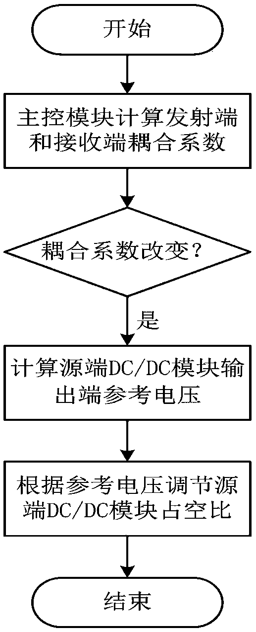
The present invention provides a wireless charging system. The wireless charging system comprises a transmitting terminal and a receiving terminal. The transmitting terminal comprises a source terminal rectification module, a source terminal DC / DC module, an inversion module, an emission coil, a detection module configured to measure an output voltage of the source terminal DC / DC module, a networkmodule, a server module configured to perform information transfer and a master control module. The receiving terminal comprises a receiving coil, a secondary terminal rectification module, a secondary terminal DC / DC module, a battery and a client module configured to input rate voltage information of the battery; the master control module controls the source terminal DC / DC module according to the rated voltage information, especially, the master control module determines a coupling coefficient when the battery is charged, and when it is determined that the coupling coefficient is changed, the output voltage of the source terminal DC / DC module is regulated to maintain the output voltage of the battery as a rated voltage. The source terminal DC / DC module is controlled to achieve instant regulation of the output voltage of the transmitting terminal in the charging process, and therefore, the problem is solved that the control of the wireless charging technology is not convenient and thecharging efficiency of the wireless charging system is ensured.

Description

technical field [0001] The invention relates to the field of wireless charging, in particular to a wireless charging system. Background technique [0002] Wireless charging technology is a new technology. Compared with the traditional wired charging method, wireless charging is more convenient and safe, especially because it is not limited by wires, chargers, sockets and other factors, wireless charging technology is very convenient to use. At present, the wireless charging technology adopts open-loop control or manual control, that is, the process is not controlled during charging, and even if it is controlled, the transmitting part is controlled manually, which reduces the convenience of wireless charging. At the same time, the resistance of the load battery will change during the charging process, or the resistance of the load battery will be different for different charging objects, which will reduce the efficiency of wireless charging and cause a serious waste of power ...

Claims


Application Information

Patent Timeline
Patent Type & Authority Applications(China)
IPC IPC(8): H02J7/02H02J7/04
CPCH02J7/025
Inventor 王庆义曹炳丁敏王雪芬
Owner CHINA UNIV OF GEOSCIENCES (WUHAN)
Learn More