Multiple anti-movement fixing device for legs

A fixed device and multiple technologies, applied in passive exercise equipment, medical science, physical therapy, etc., can solve problems such as inability to achieve rehabilitation training

Inactive Publication Date: 2020-10-20
FOURTH MILITARY MEDICAL UNIVERSITY
View PDF11 Cites 0 Cited by
  • Summary
  • Abstract
  • Description
  • Claims
  • Application Information

AI Technical Summary

Problems solved by technology

However, the leg fixing frame cannot be slightly twisted while being clamped, and the effect of rehabilitation training cannot be achieved

Method used


Image

  • Multiple anti-movement fixing device for legs
  • Multiple anti-movement fixing device for legs
  • Multiple anti-movement fixing device for legs

Examples


specific Embodiment approach 1

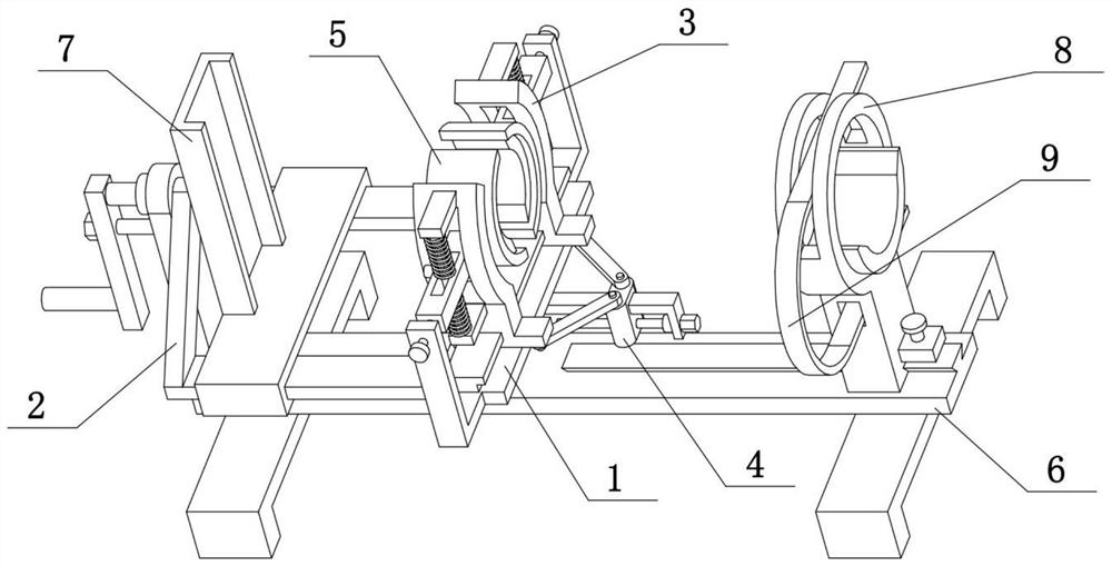
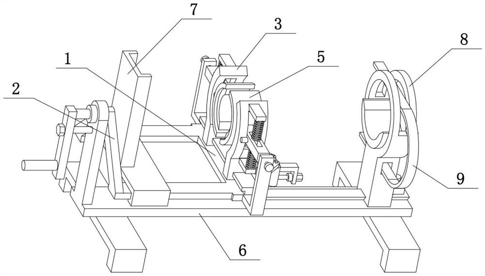
[0037] Combine below Figure 1-12 Describe this embodiment. The present invention relates to orthopedic appliances, more specifically, a multiple anti-movement fixing device for legs, including a horizontal seat 1, a T-shaped slide rail 101, an arc-shaped frame 3, an arc-shaped slide groove 301, and a convex seat 302. , spring sleeve rod 303, splint 5, square column 501, rectangular hole 503 and limit round pin 504, the present invention can clamp and fix the leg, and the leg can be slightly twisted while clamping to achieve the effect of rehabilitation training .

[0038]The upper end of the horizontal seat 1 is provided with a T-shaped slide rail 101, two arc-shaped frames 3 are provided at the front and rear, and two arc-shaped frames 3 are provided with arc-shaped slide grooves 301, and the two arc-shaped frames 3 are respectively slidably connected to the The front and rear ends of the T-shaped slide rail 101, the upper and lower ends of the outer sides of the two arc fr...

specific Embodiment approach 2

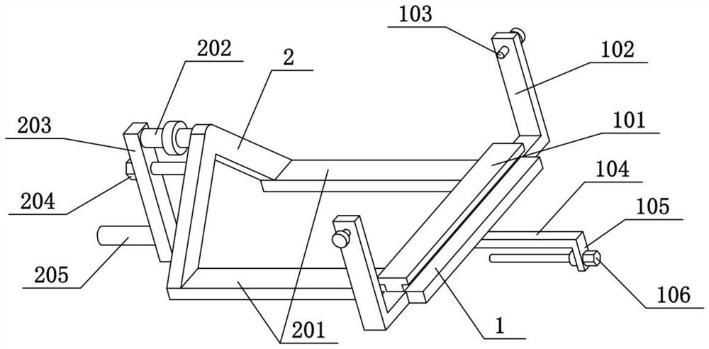
[0040] Combine below Figure 1-12 To illustrate this embodiment, the multiple anti-movement fixing device for legs also includes a middle slide rail bar 104, a slider 4 and an equal arm bar 401, the middle slide rail bar 104 is fixedly connected to the lower side of the cross seat 1, and the slide block 4 is slidably connected On the middle slide rail bar 104, the slider 4 can be fixed on the middle slide rail bar 104, two equal arm bars 401 are hingedly connected on the slide block 4, and the other ends of the two equal arm bars 401 are respectively hinged on two The lower end of arc frame 3. The slide block 4 can slide leftward or rightward on the middle slide rail bar 104, and when the slide block 4 slides leftward or rightward, the two arc-shaped frames 3 will be driven close to or far away from the two equal arm bars 401 respectively, and the two arc frames 3 will be adjusted. The spacing between the two arc-shaped frames 3 achieves the effect of clamping the legs.

specific Embodiment approach 3

[0042] Combine below Figure 1-12 To illustrate this embodiment, the multiple anti-movement fixing device for the legs also includes a convex plate 105 and a hand screw 106, the right end of the middle slide rail rod 104 is fixedly connected with the convex plate 105, and the right end of the hand screw 106 is rotatably connected to the convex plate 105, the left end of the hand screw 106 is threaded to cooperate with the slide block 4. When the hand screw 106 rotates on its own axis, it can drive the slider 4 to slide left or right to control the position of the slider 4. When the hand screw 106 does not rotate, the slider 4 is fixed by the thread self-locking effect .


PUM


Abstract

The invention relates to an orthopedic appliance, in particular to a multiple anti-motion leg fixing device. The multiple anti-motion leg fixing device comprises a transverse base, a T-shaped slidingrail, arc-shaped frames, arc-shaped sliding grooves, bosses, spring loop bars, clamping plates, square columns, rectangular holes and limiting round pins. The multiple anti-motion leg fixing device has the advantages that the leg can be clamped and fixed, and the leg can be slightly twisted while clamping to achieve a rehabilitation training effect. The upper end of the transverse base is providedwith the T-shaped sliding rail, the two arc-shaped frames are arranged front and back and are provided with the arc-shaped sliding grooves respectively, the two arc-shaped frames are slidably connected to the front and rear ends of the T-shaped sliding rail respectively, the upper and lower ends of the outer sides of the two arc-shaped frames are fixedly connected with the bosses respectively, each spring loop bar is fixedly connected between the two bosses on the same arc-shaped frame, the two spring loop bars are in sleeved connection with two compression springs, the two clamping plates are arranged front and back, the outer sides of the two clamping plates are fixedly connected with the square columns respectively, the two square columns are inserted in the two arc-shaped sliding grooves respectively, and the two square columns are fixedly connected with the two limiting round pins respectively.

Description

technical field [0001] The invention relates to an orthopedic appliance, more specifically a multiple anti-movement fixing device for legs. Background technique [0002] The application number is CN201810251861.5, which discloses a leg fixer for medical orthopedics. The invention relates to the technical field of orthopedic leg fixation, especially a leg fixer for medical orthopedics, including a mounting plate. The chain balls go out of the housing along the horizontal direction, and the chain balls are composed of a plurality of balls, two adjacent balls are connected by pull ropes, and ball grooves corresponding to the balls are provided in the circumferential direction of the turntable. When in use, put the bottom plate on the hospital bed, set the legs on the supporting plate, and tie a bandage to fix it. The supporting plate and the threaded cylinder are hingedly connected, which can turn and the legs are more comfortable. When the height needs to be adjusted, pull the...

Claims


Application Information

Patent Timeline
Patent Type & Authority Patents(China)
IPC IPC(8): A61G7/075A61H1/02
CPCA61G7/0755A61H1/0237A61H2201/0142A61H2201/0192A61H2201/1642A61H2205/10
Inventor 陶克胡大海韩军涛白晓智宁凡友
Owner FOURTH MILITARY MEDICAL UNIVERSITY
Why Eureka
Try Eureka