AI technical title is built by Patsnap AI team. It summarizes the technical point description of the patent document.
A technology for supporting devices and pillars, which is used in construction, building maintenance, building construction, etc., can solve the problem of inability to give downward force to building pillars, and achieve the effect of stable connection with the ground and preventing overturning.
Inactive Publication Date: 2019-10-25
江苏静远建设工程有限公司
View PDF6 Cites 7 Cited by
Summary
Abstract
Description
Claims
Application Information
AI Technical Summary
This helps you quickly interpret patents by identifying the three key elements:
Problems solved by technology
Method used
Benefits of technology
Problems solved by technology
However, this building support component cannot give the building pillar a downward force, so that the building pillar is more firmly connected to the ground
Method used
Image
Click on the blue label to locate the original text in one second.
Reading with bidirectional positioning of images and text.
Examples
specific Embodiment approach 1
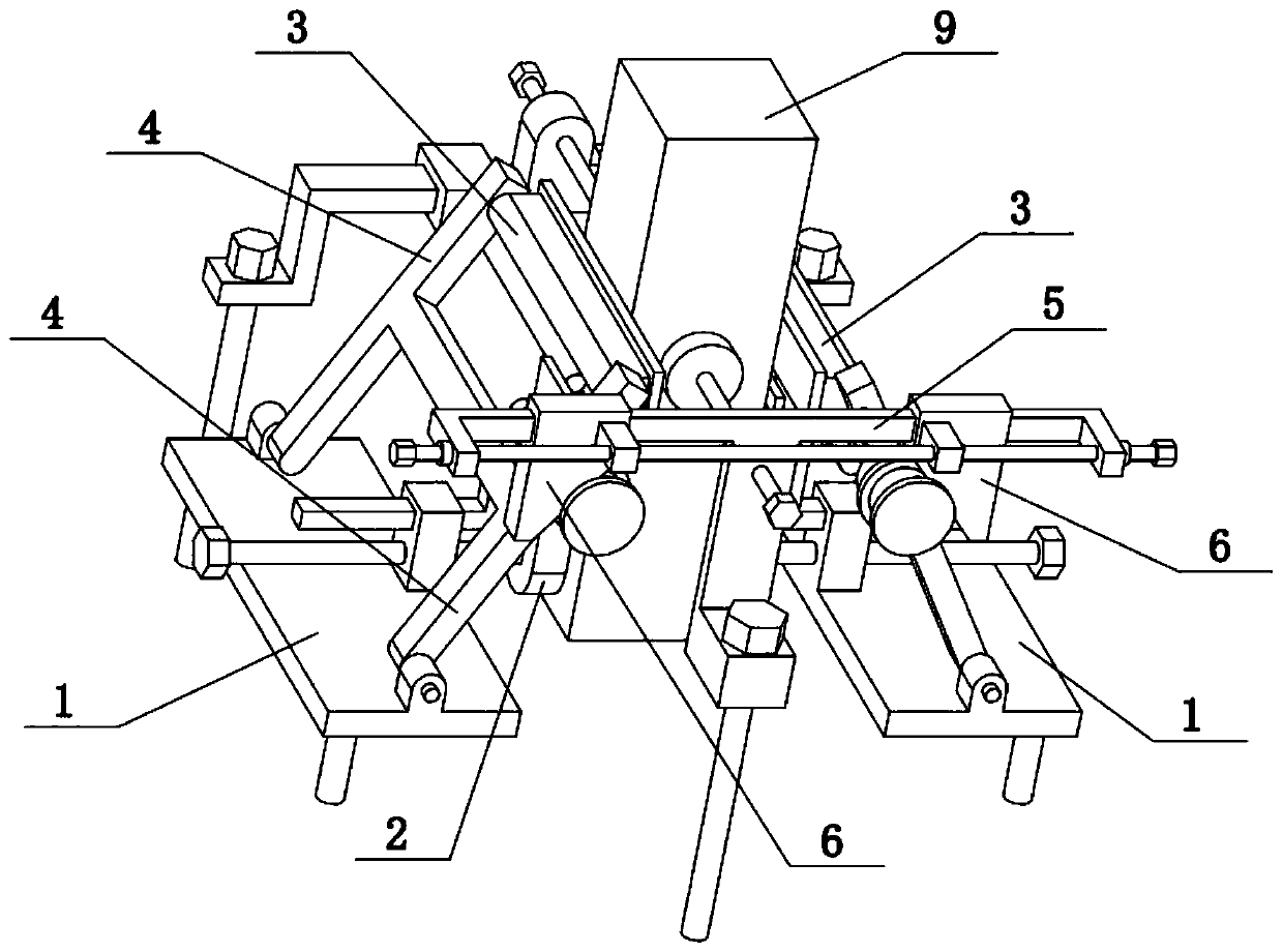
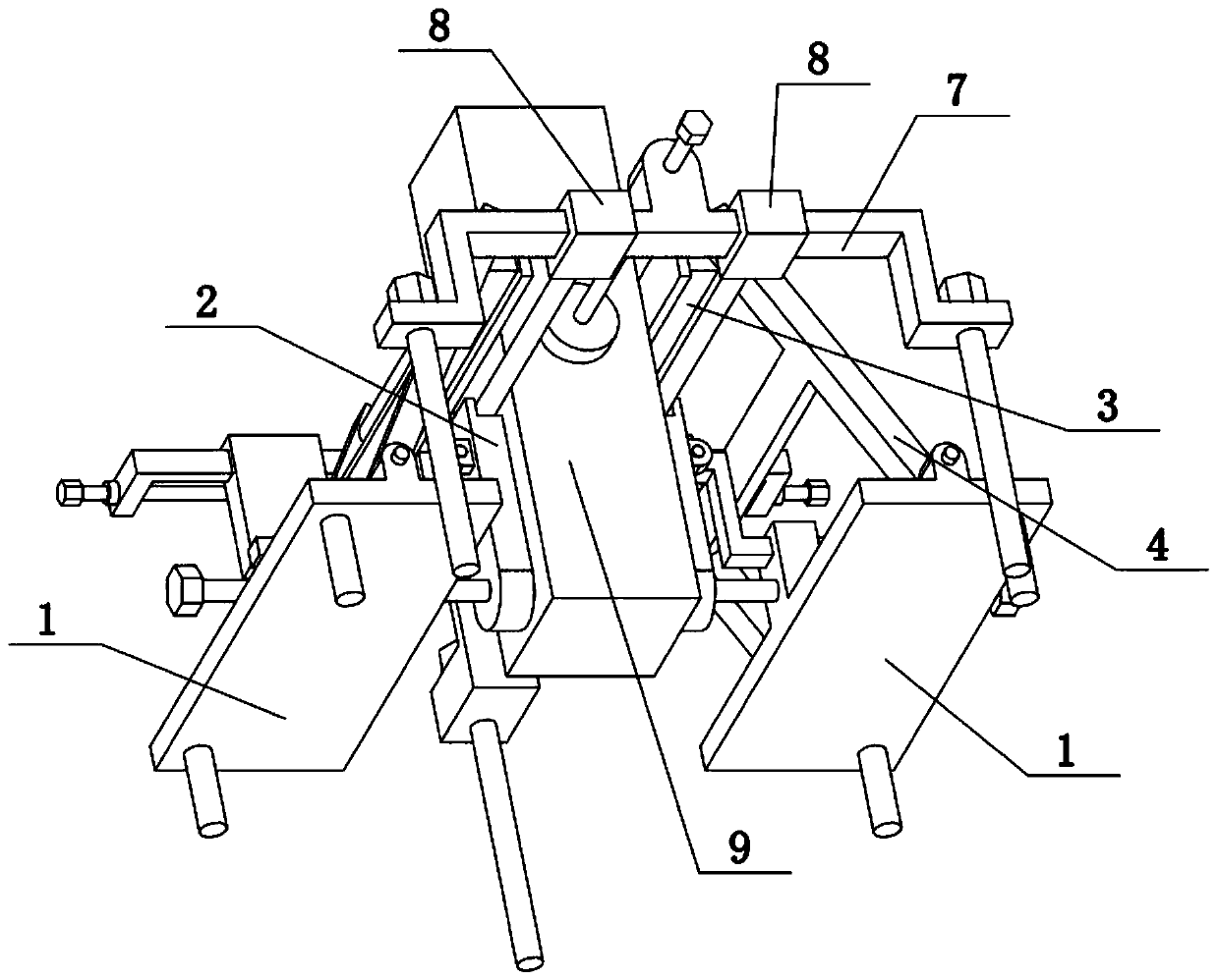
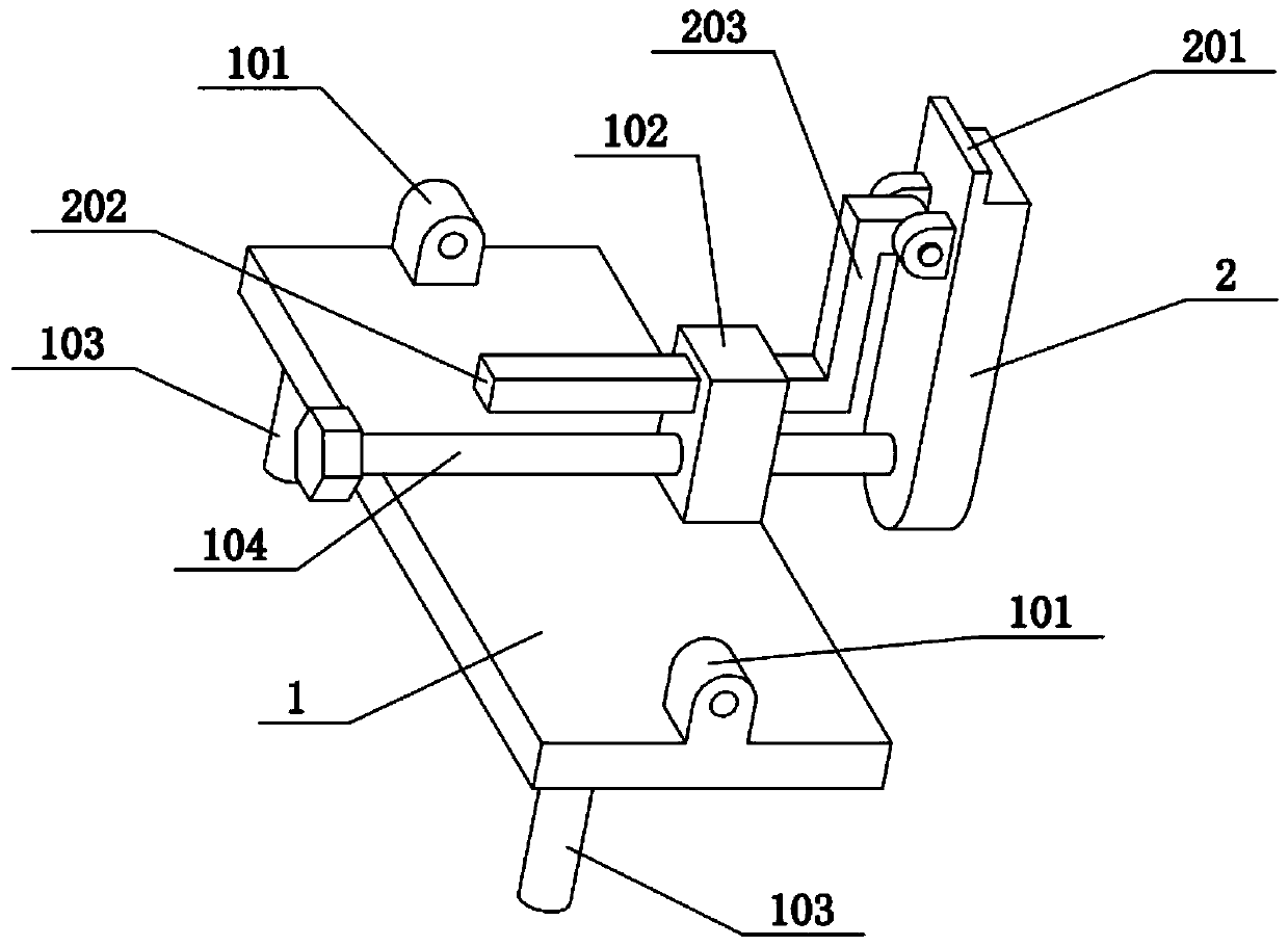
[0032] Combine below Figure 1-8 Describe this embodiment, the present invention relates to the field of construction, more specifically, a clamping and supporting device for building pillars, including a base plate 1, a fixing block 102, a thumb screw 104, a long top bar 2, a horizontal sliding post 202, a folded post 203, slide rail rod II7, ground screw II701, sliding sleeve 8 and lower pressure column 801, the present invention can clamp and support the building pillar 9 to prevent the building pillar 9 from toppling over, and the present invention can give the building pillar 9 downward force, so that the building pillars 9 are more firmly connected to the ground.
[0033]The bottom plate 1 is provided with two left and right sides, the upper ends of the two bottom plates 1 are fixedly connected with a fixed block 102, and the two fixed blocks 102 are slidably connected with a horizontal sliding column 202, and the inner ends of the two horizontal sliding columns 202 are ...
specific Embodiment approach 2
[0035] Combine below Figure 1-8 To illustrate this embodiment, the clamping and supporting device for building pillars also includes convex ribs 201, the upper ends of the two long top bars 2 are fixedly connected to the convex ribs 201, and the two pressing columns 801 are located on the two convex ribs 201. between. The function of the two convex retaining ribs 201 is to respectively limit the two pressing columns 801 and prevent the two pressing columns 801 from breaking away from the upper sides of the two long top bars 2 .
specific Embodiment approach 3
[0037] Combine below Figure 1-8 To illustrate this embodiment, the clamping and supporting device for building pillars further includes ground nails 103 , and a plurality of ground nails 103 are fixedly connected to the lower sides of the two bottom plates 1 . A plurality of ground nails 103 can be inserted into the ground, so that the two bottom plates 1 are fixed on the ground.
PUM
Abstract
The invention relates to the field of buildings, in particular to a building pillar clamping and supporting device which comprises bottom plates, fixing blocks, hand screws, long top bars, transversesliding pillars, folding pillars, a sliding rail rod II, ground inserting screws II, sliding sleeves and a lower pressing pillar. A building pillar can be clamped and supported to be prevented from toppling, downward force can be given to the building pillar, and therefore the building pillar is more stably connected with the ground. The bottom plates are arranged on the left side and the right side, the fixing blocks are fixedly connected to the upper ends of the two bottom plates, the transverse sliding pillars are slidably connected to the two fixing blocks, the folding pillars are fixedlyconnected to the inner ends of the two transverse sliding pillars, the other ends of the two folding pillars are hinged to the two long top bars correspondingly, the hand screws are connected to the two fixing blocks through threads, the two hand screws push the outer sides of the two long top bars correspondingly, the left end and the right end of the sliding rail rod II are in inserted connection with the ground inserting screws II, and the sliding rail rod II is connected with the two sliding sleeves in a sliding manner.
Description
technical field [0001] The invention relates to the construction field, in particular to a clamping and supporting device for building pillars. Background technique [0002] The steel structure building support assembly disclosed in the application number CN201820180658.9, the steel structure building support assembly, wherein there are two vertical support members and the two are vertically arranged; the end foundation plate is a plate-shaped structural member and is arranged horizontally, The lower parts of the two vertical supports are fixed on the same end base plate; the bottom outer reinforcement ribs are arranged between the vertical supports and the end base plate; the connecting plate is arranged between the two vertical supports and its At the same time, it is fixed with two vertical supports; there are two end foundation plates, which are respectively arranged at the upper near end and lower near end of the same steel structure building support assembly; there are...
Claims
Application Information
Patent Timeline
Application Date:The date an application was filed.
Publication Date:The date a patent or application was officially published.
First Publication Date:The earliest publication date of a patent with the same application number.
Issue Date:Publication date of the patent grant document.
PCT Entry Date:The Entry date of PCT National Phase.
Estimated Expiry Date:The statutory expiry date of a patent right according to the Patent Law, and it is the longest term of protection that the patent right can achieve without the termination of the patent right due to other reasons(Term extension factor has been taken into account ).
Invalid Date:Actual expiry date is based on effective date or publication date of legal transaction data of invalid patent.

