
Calibration method, device, system and terminal equipment for imaging equipment

An imaging device and calibration technology, which is applied in radio wave measurement systems, image communications, instruments, etc., can solve the problems of difficulty in implementation, long time consumption, and high requirements for calibration accuracy, so as to achieve difficulty in implementation and reduce calibration Accuracy requirements, simple and convenient calibration process

Active Publication Date: 2021-08-24
DAYA BAY NUCLEAR POWER OPERATIONS & MANAGEMENT +6
View PDF15 Cites 0 Cited by
  • Summary
  • Abstract
  • Description
  • Claims
  • Application Information

AI Technical Summary

Problems solved by technology

[0005] In view of this, the embodiment of the present application provides an imaging equipment calibration method, device, system, and terminal equipment to solve the problem that radar and imaging equipment need to be calibrated separately when radar and imaging equipment are used for monitoring in the prior art. , to adjust the coordinate system of the radar and imaging equipment to the standard coordinate system, the requirements for calibration accuracy are high, the implementation is difficult and time-consuming

Method used


Image

  • Calibration method, device, system and terminal equipment for imaging equipment
  • Calibration method, device, system and terminal equipment for imaging equipment
  • Calibration method, device, system and terminal equipment for imaging equipment

Examples


Embodiment 1

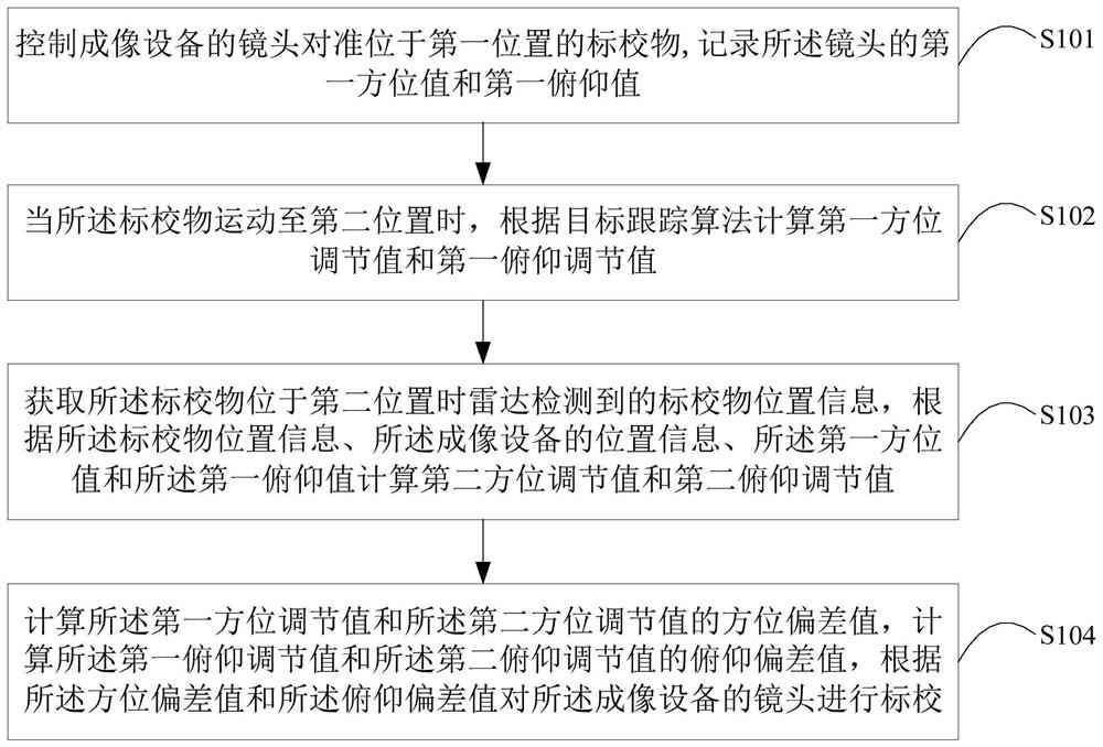
[0038] The following describes an imaging device calibration method provided in Embodiment 1 of the present application, please refer to the attached figure 1 , the imaging device calibration method in Embodiment 1 of the present application includes:

[0039] Step S101, controlling the lens of the imaging device to align with the calibration object at the first position, and recording the first azimuth value and the first pitch value of the lens;

[0040] When using radar and imaging equipment for cooperative monitoring, it is necessary to calibrate the radar and imaging equipment separately, and adjust the radar and imaging equipment to be consistent with the standard coordinate system. In the adjustment process, it is necessary to determine the standard coordinate system first, and then adjust it through professional calibration equipment. In order to ensure that the radar and imaging equipment can cooperate with each other, both of them need to achieve high calibration acc...

Embodiment 2

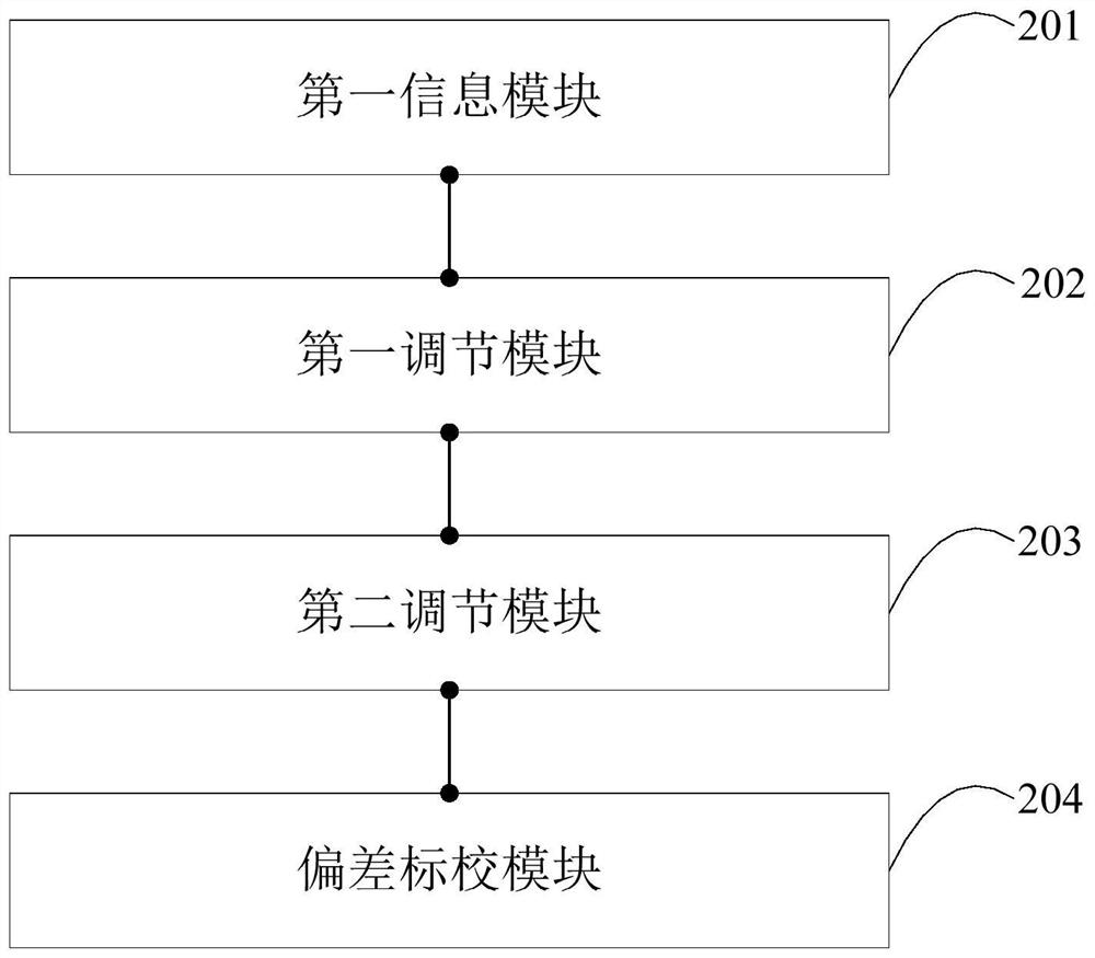
[0071] Embodiment 2 of the present application provides an imaging device calibration device. For the convenience of description, only the parts related to the present application are shown, such as figure 2 As shown, the imaging device calibration device includes,

[0072] The first information module 201 is configured to control the lens of the imaging device to align with the calibration object at the first position, and record the first azimuth value and the first pitch value of the lens;

[0073] The first adjustment module 202 is configured to calculate a first azimuth adjustment value and a first pitch adjustment value according to a target tracking algorithm when the calibration object moves to a second position;

[0074] The second adjustment module 203 is configured to acquire the position information of the calibration object detected by the radar when the calibration object is located at the second position, according to the position information of the calibration...

Embodiment 3

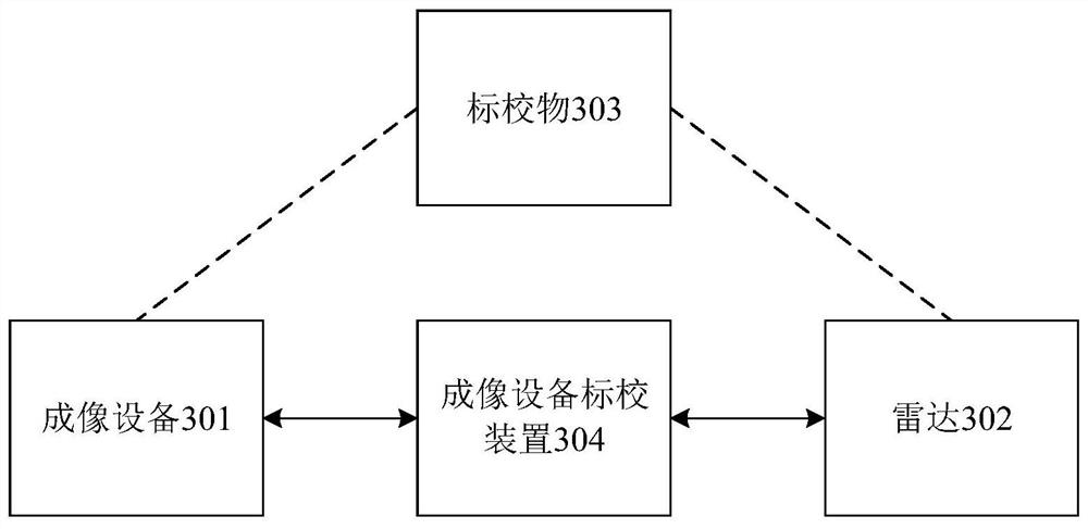
[0083] Embodiment 3 of the present application provides an imaging device calibration system. For the convenience of description, only the parts related to the present application are shown, such as image 3 As shown, the imaging device calibration system includes an imaging device 301, a radar 302, a calibration object 303, and any imaging device calibration device 304 in the above-mentioned embodiments;

[0084] The imaging device calibrating device 304 is respectively connected in communication with the imaging device 301 and the radar 302, and the imaging device calibrating device 304 is used for calibrating the imaging device according to the radar 302 and the calibration object 303 301 for calibration.

[0085] The imaging device calibrating device 304 is respectively connected to the imaging device 301 and the radar 302 in communication. In specific applications, the imaging device calibrating device 304 can be set separately from the imaging device 301. For example, th...


PUM


Abstract

This application is applicable to the technical field of environmental monitoring of nuclear power plants, and provides an imaging equipment calibration method, device, system, and terminal equipment. The method includes: controlling the lens of the imaging equipment to align with the calibration object at the first position, recording the lens The first azimuth value and the first pitch value; when the calibration object moves to the second position, calculate the first azimuth adjustment value and the first pitch adjustment value according to the target tracking algorithm; obtain the calibration object position information detected by the radar, Calculate the second azimuth adjustment value and the second pitch adjustment value; calculate the azimuth deviation value, calculate the pitch deviation value, and calibrate the lens of the imaging device according to the azimuth deviation value and the pitch deviation value. This application can solve the problem that in the prior art, when the radar and imaging equipment are used for monitoring, the radar and imaging equipment need to be calibrated separately, and the coordinate system of the radar and imaging equipment is adjusted to the standard coordinate system, which requires high calibration accuracy. It is a problem that is difficult to realize and takes a long time.

Description

technical field [0001] The application belongs to the technical field of environmental monitoring of nuclear power plants, and in particular relates to an imaging equipment calibration method, device, system and terminal equipment. Background technique [0002] With the development of science and technology, environmental monitoring technology is gradually applied in various application places. In environmental monitoring technology, multiple sensors can be used to cooperate with each other to monitor the environment. For example, radar and imaging equipment can be used to cooperate to obtain target information, and the radar can be used to obtain the position information of the target object. Azimuth and elevation angle, aim at the target, and obtain the image information of the target. [0003] When using radar and imaging equipment to monitor the environment, it is necessary to calibrate the coordinate system of the radar and imaging equipment first, so that the radar an...

Claims


Application Information

Patent Timeline
Patent Type & Authority Patents(China)
IPC IPC(8): G03B43/00G01S7/40H04N17/00
CPCG03B43/00G01S7/40H04N17/002
Inventor 潘锋王武锋赵福明李铁战黄俊
Owner DAYA BAY NUCLEAR POWER OPERATIONS & MANAGEMENT
Learn More