
Coaxial LIDAR system

A technology of laser radar and optical system, which is applied in the direction of radio wave measurement system, electromagnetic wave re-radiation, utilization of re-radiation, etc., can solve the problems of placement and inability to detect beams, achieve simple and accurate calibration, reduce installation space, Effect of Reducing Calibration Accuracy Requirements

Pending Publication Date: 2019-12-20
ROBERT BOSCH GMBH
View PDF0 Cites 0 Cited by
  • Summary
  • Abstract
  • Description
  • Claims
  • Application Information

AI Technical Summary

Problems solved by technology

Therefore the beam cannot be detected as the receiver cannot be placed in the beam without blocking the outgoing beam

Method used


Image

  • Coaxial LIDAR system
  • Coaxial LIDAR system
  • Coaxial LIDAR system

Examples


Embodiment Construction

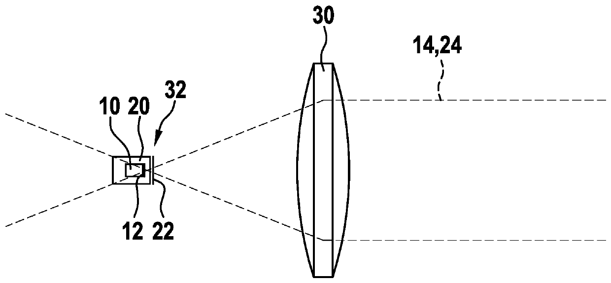
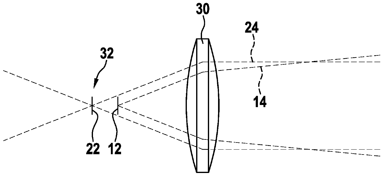
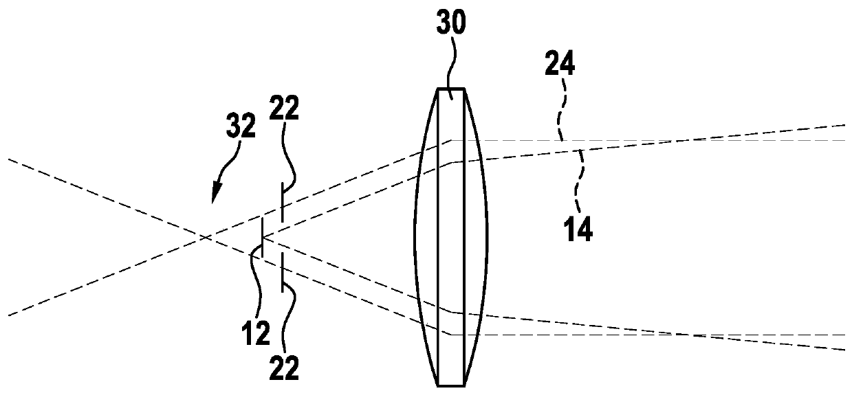
[0034] figure 1 A schematic diagram of a lidar system according to the prior art is shown in . The lidar system shown includes: a transmitter unit 10 configured to emit lidar radiation; a receiver unit 20 configured to detect incident lidar radiation; and an optical system 30 for imaging the lidar radiation, wherein the The radiation emitted by the transmitter unit 10 (i.e. by the emission surface 12 ) (transmission beam 14 ) and the radiation (reception beam 24 ) incident on the receiver unit 20 (i.e. on the detection surface 22 ) is transmitted by the optical system 30 Collinear transmission; wherein both the emission surface 12 of the transmitter unit 10 and the detection surface 22 of the receiver unit 20 are arranged in the focal point 32 of the imaging optics 30 or in its immediate surroundings.

[0035] In this case, emission beam 14 is emitted with the smallest possible divergence given the respective beam diameter. The focal point 32 of the reception beam 24 is loca...


PUM


Abstract

The invention relates to a coaxial LIDAR system. Specifically the invention relates to a coaxial LiDAR system having a reduced adjustment complexity and reduced installation space includes a transmitter unit designed to emit LiDAR radiation, a receiver unit designed to detect incident LiDAR radiation, and an optical system for imaging LiDAR radiation, the radiation emitted by the transmitter unitand the radiation from the optical system incident upon the receiver unit being transmitted in collinear form, the emitting surface of the transmitter unit being situated outside of the focus of the imaging optical system.

Description

technical field [0001] The invention relates to a coaxial laser radar system. In particular, the coaxial lidar system according to the invention requires less calibration effort and requires less installation space. Background technique [0002] Existing lidar systems (LiDAR-Systems) are usually designed to be dual-axis. This means that not only the transmitter unit but also the receiver unit has an inherent lens system for optical imaging. In these systems, the transmitter unit must be oriented very precisely relative to the receiver unit so that radiation reflected by external objects can be focused on the corresponding detector via the receiver optics and not only in this Pass by the detector. Especially when several channels need to be calibrated, this means a lot of effort in calibration. Furthermore, such a biaxial structure requires a sufficiently large installation space due to its spatially separated optical systems. [0003] In addition to biaxial systems, coa...

Claims


Application Information

Patent Timeline
Patent Type & Authority Applications(China)
IPC IPC(8): G01S7/481G01S17/06
CPCG01S7/4812G01S17/06G01S7/4817
Inventor S·施皮斯贝格尔F·安特M·萨巴尔
Owner ROBERT BOSCH GMBH
Learn More