
Iron core lamination method of iron core transformer

An iron core transformer and iron core lamination technology, applied in the field of transformers, can solve the problems of wasting time, increasing the difficulty of abrasive tool management, and affecting the progress of laminations, etc.

Active Publication Date: 2019-10-25
浦江星诚电气有限公司
View PDF8 Cites 3 Cited by
  • Summary
  • Abstract
  • Description
  • Claims
  • Application Information

AI Technical Summary

Problems solved by technology

[0003] Existing transformers are divided into core-type transformers and shell-type transformers according to the core form. In the traditional core-type transformer core lamination process, different specifications of core transformers need to be replaced with different lamination devices. Increased difficulty, while wasting time during the replacement process affects the lamination progress

Method used


Image

  • Iron core lamination method of iron core transformer
  • Iron core lamination method of iron core transformer
  • Iron core lamination method of iron core transformer

Examples


Embodiment Construction

[0028] In order to enable those skilled in the art to better understand the solutions of the present invention, the technical solutions in the embodiments of the present invention will be clearly and completely described below in conjunction with the drawings in the embodiments of the present invention. Obviously, the described embodiments are only It is a part of embodiments of the present invention, but not all embodiments. Based on the embodiments of the present invention, all other embodiments obtained by persons of ordinary skill in the art without making creative efforts shall fall within the protection scope of the present invention.

[0029] A method for lamination of iron core transformer iron core, comprising the following steps:

[0030] a. Preparation before lamination: Prepare materials, spare parts, tools and lamination devices required in the lamination process;

[0031] b. Device adjustment: adjust the lamination device according to the iron core lamination re...


PUM


Abstract

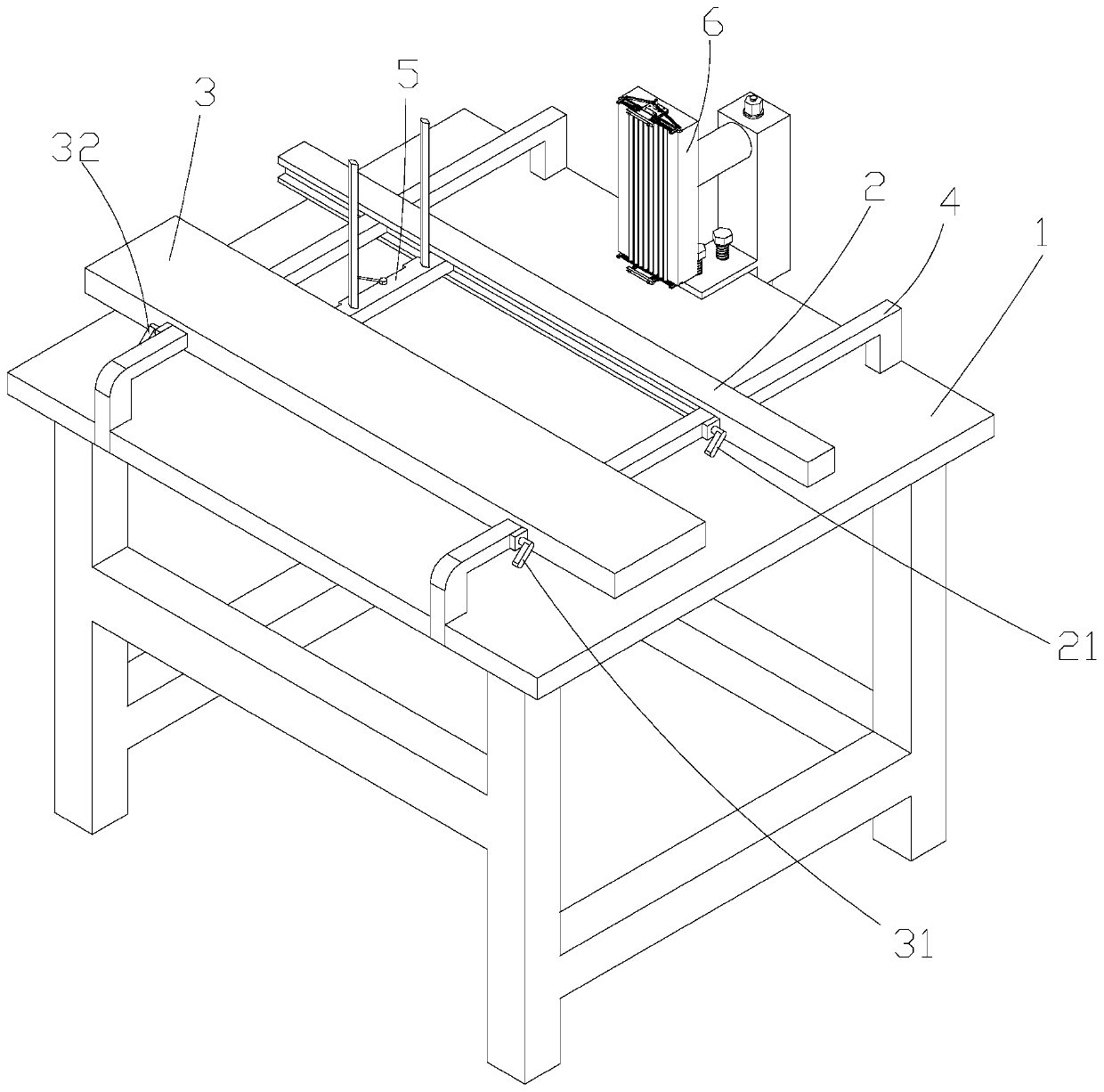
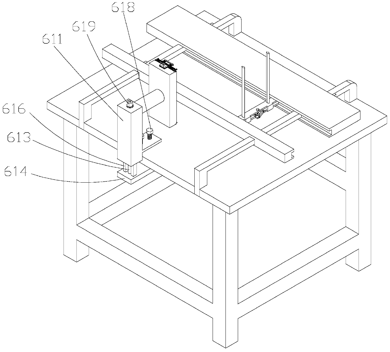
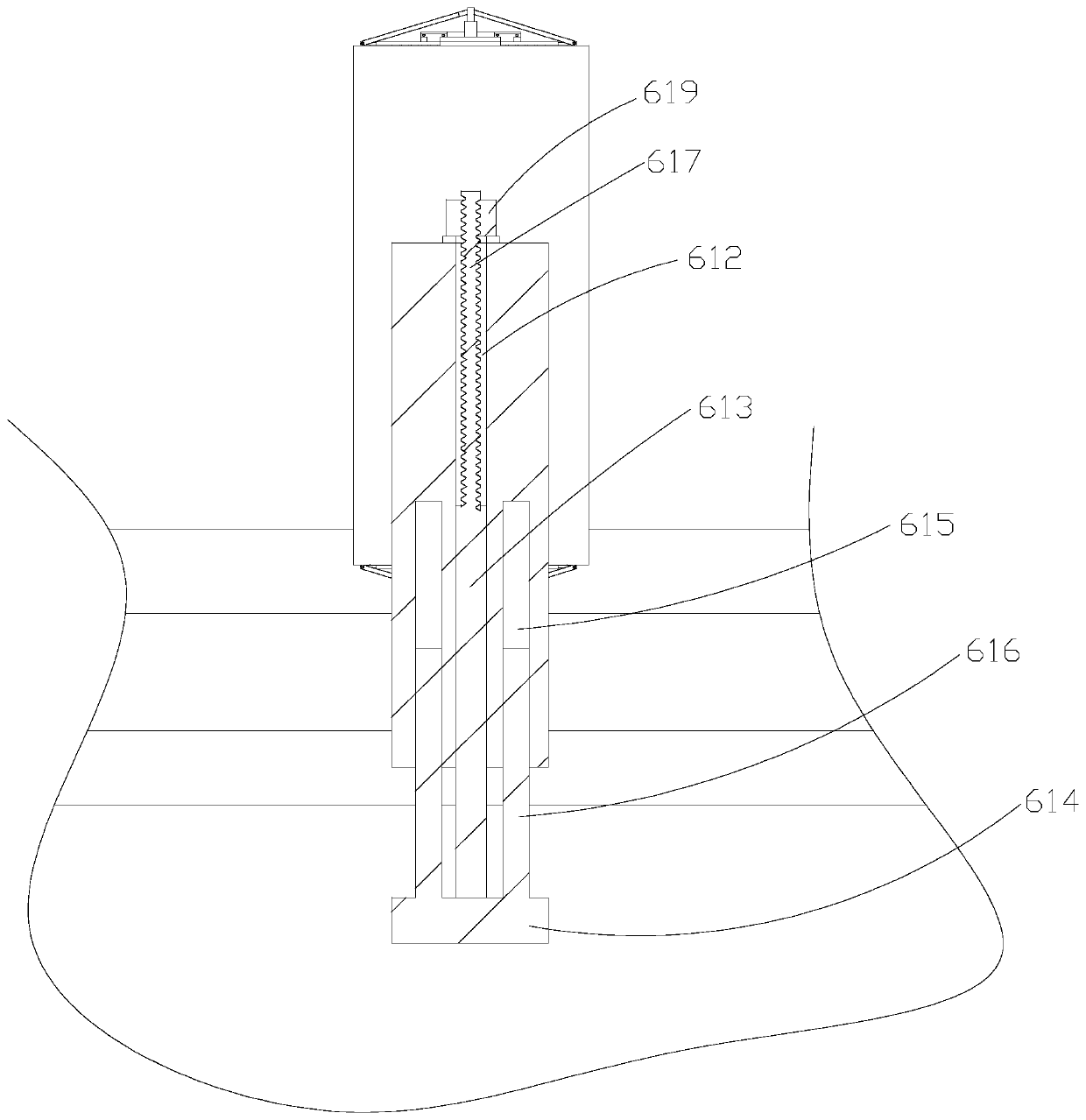
The invention discloses an iron core lamination method of an iron core transformer. The method comprises the following steps of preparation before lamination, device adjustment, lamination of an intermediate column sheet, lower yoke sheet lamination, rim charge lamination and upper yoke sheet lamination. In the step of device adjustment, mainly a lamination device is adjusted. The lamination device comprises a workbench, a first shoe plate positioned over the workbench, a second shoe plate arranged in parallel with the first shoe plate, a fixed guide rail penetrating both the first and secondshoe plates and fixed on the workbench, a first limiting leaning post arranged on both the first and second shoe plates, and a second limiting leaning post for limiting the tip of an intermediate column sheet. Iron cores of different specifications can be laminated via the method.

Description

technical field [0001] The invention relates to the technical field of transformers, in particular to an iron core lamination method for an iron core transformer. Background technique [0002] At present, in the process of electric energy transmission, a relatively low voltage is first obtained through a generator, and a transformer is used to boost the transmission voltage at the transmission end of the power plant to obtain a higher transmission voltage. Press to the appropriate range. [0003] Existing transformers are divided into core-type transformers and shell-type transformers according to the core form. In the traditional core-type transformer core lamination process, different specifications of core transformers need to be replaced with different lamination devices. Increase the difficulty, while wasting time in the replacement process affects the lamination progress. Contents of the invention [0004] In order to overcome the deficiencies of the prior art, the...

Claims


Application Information

Patent Timeline
Patent Type & Authority Applications(China)
IPC IPC(8): H01F41/02
CPCH01F41/0233
Inventor 费东晖吴海清
Owner 浦江星诚电气有限公司
Learn More