
Novel diffusion furnace battery piece conveying device

A conveying device and diffusion furnace technology, which is applied in the direction of conveyor objects, transportation and packaging, circuits, etc., can solve problems such as unfavorable fixation, increased frictional resistance, and defective sheets, so as to improve the yield rate, prevent left and right deviation, reduce The effect of DOWN machine time

Pending Publication Date: 2017-11-03
TONGWEI SOLAR (ANHUI) CO LTD
View PDF8 Cites 2 Cited by
  • Summary
  • Abstract
  • Description
  • Claims
  • Application Information

AI Technical Summary

Problems solved by technology

[0002] During the production process of photovoltaic modules, the cells need to be diffused, so the cells need to be transported into the diffusion furnace, but the diffusion furnace of the cells often has an overload alarm. If the treatment is not timely, the silicon chips will stay in the tube. If the time is too long, there will be bad films
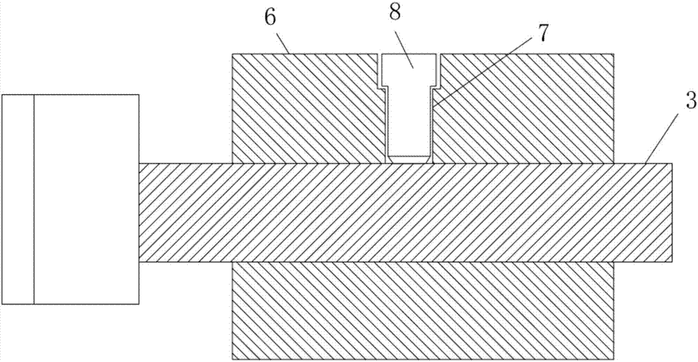
[0003] In the prior art, if the specification attached figure 1 As shown, the original fixed surface on the center shaft is a smooth flat surface, and it is necessary to use the top screw to push the fixed surface to prevent the synchronous wheel from shifting. However, the smooth fixed surface is easy to make the top screw loose, which is very unfavorable fixed, which causes the synchronous wheel to shift to one side, which increases the friction resistance during the movement, which also causes the occurrence of the above-mentioned push boat overload alarm

Method used


Image

  • Novel diffusion furnace battery piece conveying device
  • Novel diffusion furnace battery piece conveying device
  • Novel diffusion furnace battery piece conveying device

Examples


Embodiment Construction

[0018] The following will clearly and completely describe the technical solutions in the embodiments of the present invention with reference to the accompanying drawings in the embodiments of the present invention. Obviously, the described embodiments are only some, not all, embodiments of the present invention. Based on the embodiments of the present invention, all other embodiments obtained by persons of ordinary skill in the art without making creative efforts belong to the protection scope of the present invention.

[0019] see Figure 1-4 , the present invention provides a technical solution:

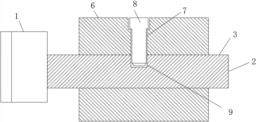
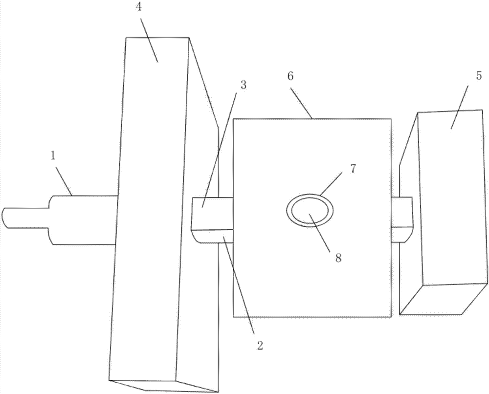
[0020] A new diffusion furnace battery sheet conveying device, including a central shaft and a synchronous wheel 6, the central shaft includes a central shaft fixed end 1 and a central shaft installation end 2 that are fixedly connected to each other, and the central shaft fixed end 1 is used for mutual fixing with the motor, through The motor drives the fixed end 1 of the central...


PUM


Abstract

Disclosed is a novel diffusion furnace battery piece conveying device, comprising a central shaft and a synchronizing wheel. A fixing surface is arranged on an outer side wall of a mounting end of the central shaft, and two ends of the mounting end of the central shaft are rotatably inserted into a left mounting frame and a right mounting frame respectively. The synchronizing wheel is sleeved on the mounting end of the central shaft between the left mounting frame and the right mounting frame. An insertion hole penetrates through the synchronizing wheel, a drilling hole is formed in the fixing surface in correspondence to the insertion hole, a jackscrew is inserted into the insertion hole, and an end, close to the mounting end of the central shaft, of the jackscrew extends into the drilling hole. By changing a fixing manner of the synchronizing wheel, the fixing surface of the central shaft capable of more firmly fixing the synchronizing wheel is designed, the drilling hole is formed in the surface of the fixing surface, the jackscrew is inserted into the insertion hole of the synchronizing wheel and extends into the drilling hole, and therefore the synchronizing wheel can be effectively prevented from shifting leftwards and rightwards. Thus, a situation of a pusher overload alarm of a diffusion furnace is avoided, the downtime of the diffusion furnace is reasonably shortened, and therefore the yield during diffusion of silicon wafers can be improved.

Description

technical field [0001] The invention relates to the technical field of cell diffusion equipment, in particular to a novel diffusion furnace cell conveying device. Background technique [0002] During the production process of photovoltaic modules, the cells need to be diffused, so the cells need to be transported into the diffusion furnace, but the diffusion furnace of the cells often has an overload alarm. If the treatment is not timely, the silicon chips will stay in the tube. If the time is too long, bad films will appear. [0003] In the prior art, such as the attached figure 1 As shown, the original fixed surface on the center shaft is a smooth flat surface, and it is necessary to use the top screw to push the fixed surface to prevent the synchronous wheel from shifting. However, the smooth fixed surface is easy to make the top screw loose, which is very unfavorable fixed, thereby causing the synchronous wheel to shift to one side, increasing the frictional resistance...

Claims


Application Information

Patent Timeline
Patent Type & Authority Applications(China)
IPC IPC(8): H01L21/677H01L31/18
CPCH01L31/18H01L21/67742Y02P70/50
Inventor 王勤振吴文明马东方
Owner TONGWEI SOLAR (ANHUI) CO LTD
Learn More