Double cam mechanism

A cam mechanism and cam technology, applied in the direction of cams, mechanical equipment, belts/chains/gears, etc., can solve the problems that the maximum pressure angle of the cam exceeds the allowable limit, the cam cannot be arranged, self-locking, etc.

Inactive Publication Date: 2014-04-30
CHONGQING TIANZHIDAO SCI & TECH DEV
View PDF0 Cites 2 Cited by
  • Summary
  • Abstract
  • Description
  • Claims
  • Application Information

AI Technical Summary

Problems solved by technology

[0002] Existing cams usually use larger cams in order to obtain larger strokes, but for some small equipment, it is impossible to arrange larger cams, and designers generally increase the pressure angle of the cams to achieve the increase from The stroke of the moving parts, but this method often makes the maximum pressure angle of the cam exceed the allowable limit, and self-locking phenomenon occurs

Method used


Image

  • Double cam mechanism

Examples


Embodiment Construction

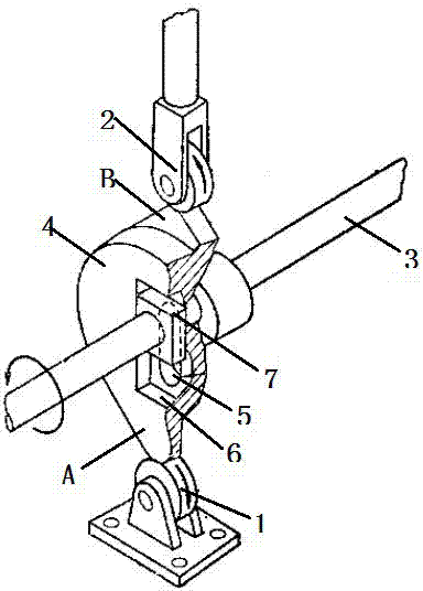
[0009] Such as figure 1 Shown: double cam mechanism, including fixed roller 1, driven roller 2, camshaft 3 and double cam 4, the center of double cam 4 is provided with a square groove 6 along the long diameter direction of double cam 4, The square groove 6 runs through a slotted hole 5, and the double cam 4 is assembled on the camshaft 3 through the slotted hole 5, and the camshaft 3 is fixed with a limit block 7 at the direction groove 6; the upper end of the double cam 4 It consists of two cams with different base circle radii, cam A and cam B in the figure, cam B with larger base circle radius is in contact with driven roller 2, and cam A is in contact with fixed roller. One side of the center of the double cam 4 is provided with a square groove 6 , and the cam shaft 3 is fixed with a limit block 7 at the position corresponding to the square groove 6 .

[0010] The above description is only a detailed description of the preferred embodiments of the present invention, an...


PUM


Abstract

The invention belongs to the technical field of electric switches, and particularly relates to a double cam mechanism which comprises a fixed roller, a driven roller, a cam shaft and a double cam. A slotted hole is formed in the center of the double cam along the long diameter direction of the cam, the double cam is assembled on the cam shaft through the slotted hole, the double cam includes two cams with different base circle radiuses, the cam with the large base circle radius contacts with the driven roller, and the cam with the small base circle radius contacts with the fixed roller. Strokes of driven components of the cams can be enlarged under the permissive condition of the maximum pressure angles of the cams.

Description

technical field [0001] The invention belongs to the technical field of transmission devices. Background technique [0002] Existing cams usually use larger cams in order to obtain larger strokes, but for some small equipment, it is impossible to arrange larger cams, and designers generally increase the pressure angle of the cams to achieve the increase from However, this method often causes the maximum pressure angle of the cam to exceed the allowable limit, and self-locking occurs. Contents of the invention [0003] The present invention intends to provide a double cam mechanism which makes it possible to increase the stroke of the driven member. [0004] The object of the present invention can be achieved through the following measures: the double cam mechanism includes a fixed roller, a driven roller and a camshaft, and also includes a double cam, the center of the double cam has a slotted hole arranged along the long diameter direction of the cam, The double cam is a...

Claims


Application Information

Patent Timeline
IPC IPC(8): F16H53/00
CPCF16H53/08
Inventor 姜静慧
Owner CHONGQING TIANZHIDAO SCI & TECH DEV
Why Eureka
Try Eureka