Check patentability & draft patents in minutes with Patsnap Eureka AI!

Mapped object positioning pan/tilt control method

A control method and target positioning technology, which are applied to color TV parts, TV system parts, TV and other directions, and can solve the problems of inaccurate zoom factor, non-linear relationship between object distance and image size, and inaccurate calculation.

Active Publication Date: 2021-06-18
威斯泰(苏州)智能科技有限公司
View PDF0 Cites 0 Cited by
  • Summary
  • Abstract
  • Description
  • Claims
  • Application Information

AI Technical Summary

Problems solved by technology

Due to the inaccurate zoom factor and the different sizes of the images presented at different focal lengths, the pixels of 30x zoom are used to calculate the pixels of 1x zoom, resulting in inaccurate calculation
[0021] 2. Object distance and imaging size are not linear
The size of the image presented by the object at different distances is also different, and the size of the image presented is not linear, resulting in inaccurate calculations
[0022] 3. The relationship between zoom and imaging size is not linear
[0023] 4. Using the image size to calculate the size of the object will cause error amplification

Method used


Image

  • Mapped object positioning pan/tilt control method
  • Mapped object positioning pan/tilt control method
  • Mapped object positioning pan/tilt control method

Examples


Embodiment Construction

[0069] The present invention will be further described below in conjunction with the accompanying drawings and specific embodiments, so that those skilled in the art can better understand the present invention and implement it, but the examples given are not intended to limit the present invention.

[0070] The invention relates to the fields of image processing, motion tracking, computer vision, pan-tilt control, lens optics, etc., and more specifically relates to an automatic camera tracking system based on static and dynamic recognition of single-lens images. The computer program is used to locate the coordinates of the video surveillance pan-tilt. Solved the problem that the gimbal cannot be accurate but track the target, and the positioning is not accurate.

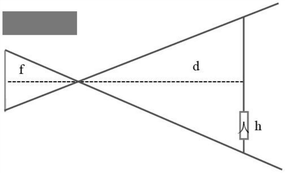
[0071] For example: laser obstacle removal, electric power inspection, when the robot takes pictures of the instrument, the gimbal will move the instrument to the center of the image after multiple rotations, it is d...


PUM


Abstract

The invention discloses a method for controlling a mapped object positioning pan-tilt. A mapping object positioning cloud platform control method of the present invention comprises: determining a point on the image; acquiring the pixel coordinates of the point; acquiring the position angle of the platform; starting to rotate the platform; finding the same point in the image again; The current position and angle of the pan / tilt; calculate the corresponding relationship between the pan / tilt angle and the pixel point through the parameters; wait for the pan / tilt to be controlled; input the coordinate points in the new image; calculate the angle of the pan / tilt control. Beneficial effects of the present invention: the present invention improves the calculation accuracy of controlling the angle from the pan-tilt to the target.

Description

technical field [0001] The invention relates to the field of cloud platforms, in particular to a method for controlling a mapped target positioning platform. Background technique [0002] As the concept of artificial intelligence becomes more and more popular, instrument recognition, motion tracking, and target positioning all require precise control of the gimbal. [0003] At present, the control algorithm of the pan / tilt basically adopts the lens optical calculation method. [0004] Lens optics calculation method: [0005] but: [0006] The focal length of the camera lens: f (mm), the detector pixel size r (um), the distance between the target and the lens d (m), and the height of the human target is h (m), then the number of pixels occupied by the human body image in the vertical direction is x for: [0007] [0008] Deduced: [0009] [0010] The focal length of the current camera is 4.5mm under the zoom factor of 1, and Z is the zoom factor of the camera. It ...

Claims


Application Information

Patent Timeline
Patent Type & Authority Patents(China)
IPC IPC(8): H04N5/232
CPCH04N23/64H04N23/695
Inventor 刘剑薄旭谷诗
Owner 威斯泰(苏州)智能科技有限公司
Features
  • R&D
  • Intellectual Property
  • Life Sciences
  • Materials
  • Tech Scout
  • Unparalleled Data Quality
  • Higher Quality Content
  • 60% Fewer Hallucinations
Learn More