
Method for Measuring Fluid Velocity

A measurement method, fluid velocity technology, applied in fluid velocity measurement, measurement flow/mass flow, measurement device, etc.

Active Publication Date: 2021-09-21
SAGEMCOM ENERGY & TELECOM
View PDF0 Cites 0 Cited by
  • Summary
  • Abstract
  • Description
  • Claims
  • Application Information

AI Technical Summary

Problems solved by technology

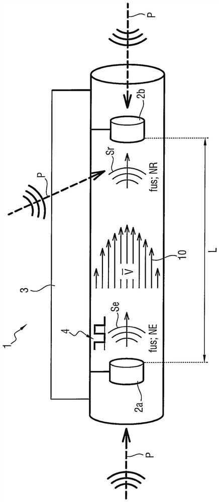
[0020] Interference P may occur (eg figure 1 shown), such as anomalies or spoofing attempts, that degrade the operation of the measuring device of the fluid flow meter

Method used


Image

  • Method for Measuring Fluid Velocity
  • Method for Measuring Fluid Velocity
  • Method for Measuring Fluid Velocity

Examples


Embodiment Construction

[0045] In this example, the inventive method for measuring fluid velocity is implemented in an ultrasonic water meter.

[0046] Ultrasonic water meters include both the conduit through which water delivered by the distribution network flows to the facility, and the figure 1 Water velocity measuring equipment of the kind shown.

[0047] Water flows from upstream to downstream in a conduit, such as figure 1 Indicated by the direction of the arrow 10 visible in .

[0048] The measuring device comprises a measuring module 3, a first transducer 2a and a second transducer 2b.

[0049] The measurement module 3 comprises processor means comprising an intelligent processor assembly adapted to execute the instructions of the program in order to carry out the individual steps of the measurement method of the invention. In this example, the smart component is a microcontroller, but it could be some other component such as a processor or a field-programmable gate array (FPGA).

[0050]...


PUM


Abstract

A method for measuring the velocity of a fluid comprising the steps of: generating a plurality of pseudorandom frequencies (fus n); for each pseudorandom frequency (fus n), producing a measurement of travel time and using The resulting measurement of frequency is used to assess the velocity of the fluid. In order to evaluate the accuracy of the time measurements, inaccurate measurements are identified and the frequency with the lowest number of inaccurate measurements is selected as the transmit frequency with the highest accuracy.

Description

technical field [0001] The present invention relates to the field of methods of measuring fluid velocity. Background technique [0002] In order to measure the flow velocity of a fluid flowing in a pipe, an ultrasonic flowmeter generally utilizes a device for measuring the velocity of the fluid by transmitting and receiving ultrasonic measurement signals. [0003] Such measuring devices comprise conduits connected to pipes in which fluid flows. In order to measure the velocity of the fluid, an ultrasonic measurement signal is emitted into the catheter to follow a path of defined length, the travel time taken by the ultrasonic measurement signal to travel along the path of defined length from upstream to downstream and from downstream to upstream is measured, And the velocity of the fluid is estimated notably based on this defined length and on the difference between the travel times. [0004] For water meters, three main types of measuring devices are in use. [0005] The...

Claims


Application Information

Patent Timeline
Patent Type & Authority Patents(China)
IPC IPC(8): G01P5/24G01P21/02G01F1/66G01D4/00
CPCG01P5/245G01P21/025G01F1/667G01F1/666G01P5/18G01F1/66G01F1/665G01P5/00G01F3/00
Inventor H·泰布尔勒
Owner SAGEMCOM ENERGY & TELECOM
Learn More