
Equipment power monitoring device and method

A technology of equipment power consumption and monitoring devices, which is applied in the direction of power consumption devices, measuring devices, program control, etc., can solve problems such as waste, cabinet resource utilization rate not reaching the cabinet, and ensure safe operation of equipment, so as to avoid waste and facilitate equipment Configure and ensure the effect of work safety

Inactive Publication Date: 2019-10-29
INSPUR BUSINESS MACHINE CO LTD
View PDF11 Cites 0 Cited by
  • Summary
  • Abstract
  • Description
  • Claims
  • Application Information

AI Technical Summary

Problems solved by technology

In fact, the maximum power consumption of the device when it leaves the factory will be higher than the actual power consumption
Therefore, in practical applications, if the layout is based on the sum of the maximum power consumption, the utilization rate of the cabinet resources by the equipment will not reach the upper limit that the cabinet can carry, resulting in great waste
However, if the actual power consumption of the equipment is determined based on experience to achieve the maximum utilization of the power consumption of the cabinet, and the cabinet is overconfigured to a certain extent, the entire cabinet may be disconnected due to the power consumption exceeding the maximum value. Electricity and other uncontrollable safety hazards
[0004] Therefore, the above two methods proposed in the prior art cannot reasonably configure equipment for the cabinet according to the actual usage of the power consumption of the cabinet, and cannot maximize the power consumption of the cabinet while ensuring the safe operation of the equipment, thereby Avoid the waste of cabinet power resources

Method used


Image

  • Equipment power monitoring device and method
  • Equipment power monitoring device and method
  • Equipment power monitoring device and method

Examples


Embodiment Construction

[0033] The following will clearly and completely describe the technical solutions in the embodiments of the present invention in conjunction with the accompanying drawings in the embodiments of the present invention. Obviously, the described embodiments are only some of the embodiments of the present invention, not all of them. Based on the embodiments of the present invention, all other embodiments obtained by persons of ordinary skill in the art without making creative efforts belong to the protection scope of the present invention.

[0034] The core of the present invention is to provide a device and method for monitoring equipment power consumption, which can collect power consumption data of the equipment occupied by the cabinet, and display the resource occupation information of the cabinet through the display, so as to realize the monitoring of the power consumption of the equipment occupied by the cabinet, so that the staff can clearly understand , Intuitively understan...

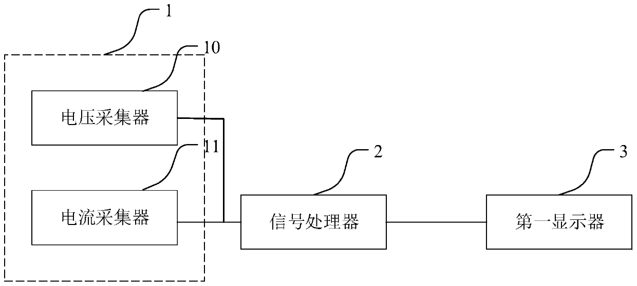

PUM


Abstract

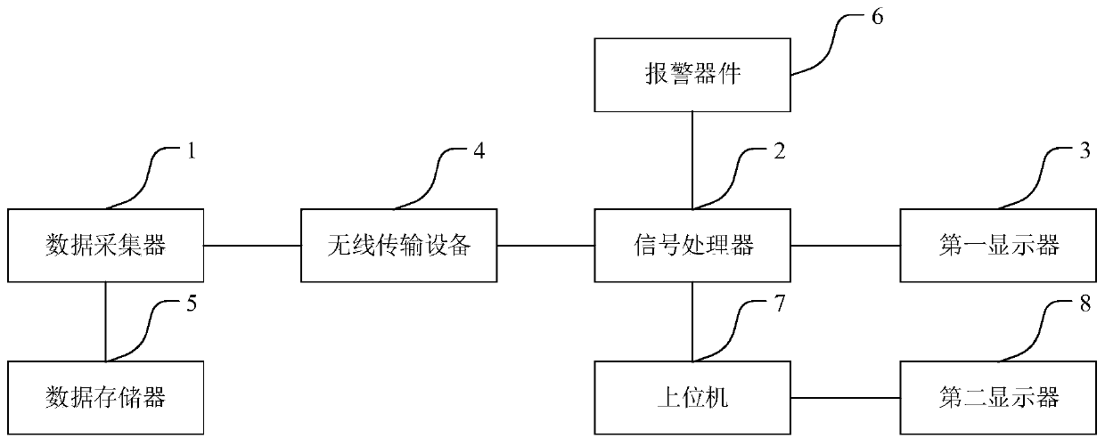
The invention discloses an equipment power monitoring device, comprising a data collector connected to the power supply end of the equipment and configured to collect the power data of a cabinet occupied by the power supply end; a signal processor connected with the data collector and configured to receive the power data and generate a display instruction according to the power data; and a first display connected to the signal processor and configured to receive the display instruction and display the resource occupation information of the cabinet. A worker can clearly and intuitively understand the actual power of the cabinet by viewing the equipment-occupied resource information of the cabinet displayed on the first display so as to configure the cabinet reasonably. In addition, the present invention also provides an equipment power monitoring method corresponding to the device, which has the same beneficial effects.

Description

technical field [0001] The invention relates to the field of automatic control, in particular to a device and method for monitoring power consumption of equipment. Background technique [0002] With the rapid development and wide application of big data and cloud computing, large-scale centralized computer rooms have become the best means for resource sharing and efficient management. There are multiple cabinets distributed in the centralized computer room, and each cabinet can hold multiple IT devices. How to allocate an appropriate number of IT devices to each cabinet within the total power consumption range that the cabinet can carry, so as to improve the resource utilization of the cabinet as much as possible while ensuring safety has become an important issue at present. [0003] At present, the evaluation and management method of the total power consumption of the cabinet is relatively simple. Usually, planning is carried out by referring to the sum of the maximum pow...

Claims


Application Information

Patent Timeline
Patent Type & Authority Applications(China)
IPC IPC(8): G05B19/042G01R21/00
CPCG01R21/00G05B19/042
Inventor 杨宇
Owner INSPUR BUSINESS MACHINE CO LTD
Learn More